Cylinder Block and Components Assembly Overview
Cylinder Block and Components Assembly Overview
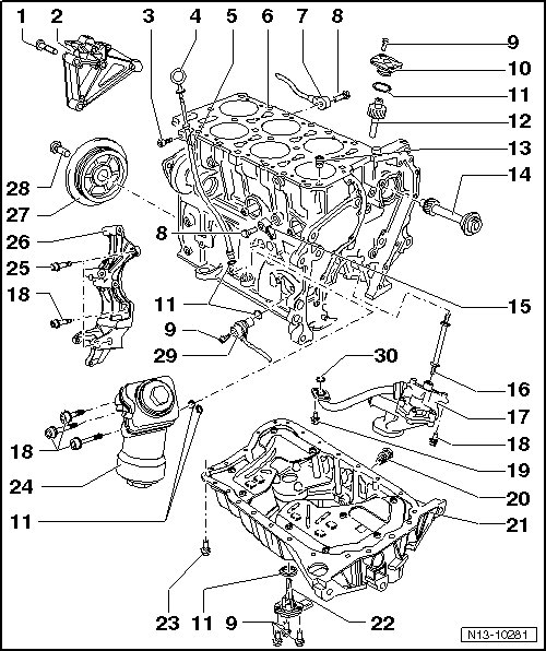
1 Bolt, 45 Nm
2 Engine Mount Bracket
3 Bolt, 5 Nm
• To the intake manifold.
4 Oil Dipstick
• Oil level must not be above the Max. mark!
• Markings, refer to => [ Oil Level Indicator Markings ] Oil Level Indicator Markings.
5 Guide Tube
• For the oil dipstick.
• Secured by a bolt - item 3 - to the intake manifold.
6 Cylinder Block
• Sealing flange assembly overview, refer to => [ Sealing Flange Assembly Overview ] Service and Repair.
• Crankshaft assembly overview, refer to => [ Crankshaft Assembly Overview ] Crankshaft Assembly Overview.
• Piston and connecting rod assembly overview, refer to => [ Piston and Connecting Rod Assembly Overview ] Piston and Connecting Rod Assembly Overview.
7 Knock Sensor (KS) 1 (G61)
• Component location: Between cylinders 1 and 3.
8 Bolt, 20 Nm
• Tightening specification affects the function of the KS.
9 Bolt, 10 Nm
10 Oil Pump Drive Cover
11 O-ring
• Always replace.
• Lubricate before assembling.
12 Oil Pump Drive
13 Oil Check Valve, 5 Nm
• Note the installed position.
• Clean if badly contaminated.
• See note in => [ General Repair Information ] Description and Operation.
14 Intermediate Shaft
15 Knock Sensor (KS) 2 (G66)
• Component location: Between cylinders 4 and 6.
16 Input Shaft
• For the oil pump drive.
17 Oil Pump
• Oil pump assembly overview, refer to => [ Oil Pump Assembly Overview ] Service and Repair.
18 Bolt, 23 Nm
19 Bolt, 8 Nm
• Always replace.
20 Oil Pan Drain Plug, 30 Nm
• Replace if the washer is permanent.
21 Oil Pan
• Removing and installing, refer to => [ Oil Pan ] Oil Pan.
22 Oil Level Thermal Sensor (G266)
23 Bolt, 12 Nm
24 Oil Filter Housing
• Oil filter housing assembly overview, refer to => [ Oil Filter Housing Assembly Overview ] Service and Repair.
• Coolant hose connection diagram, refer to => [ Coolant Hose Connection Diagram ] [1][2]Diagrams.
25 Bolt, 23 Nm
• Centering bolt.
26 Accessory Bracket
• For the generator , Air Conditioning (A/C) compressor, and power steering pump.
27 Vibration Damper
• Use the counter holder tool (T10069) to remove and install. Refer to => [ Lock The Vibration Damper Using The T10069 ].
• Removing and installing the ribbed belt. Refer to => [ Ribbed Belt ] Ribbed Belt.
28 Bolt, 100 Nm + 180° (1/2) additional turn
• Always replace.
• Use the counter holder tool (T10069) to loosen and tighten. Refer to => [ Lock The Vibration Damper Using The T10069 ].
• Tighten using the torque wrench (VAG 1601).
29 Engine Speed (RPM) Sensor (G28)
30 Seal
• Replace if damaged.
Lock The Vibration Damper Using The T10069
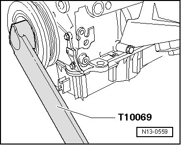
• Vibration damper bolt must be replaced.
• Tighten the bolt using the torque wrench (VAG 1601 ).