Procedures
Crankshaft, Locking
=> [ to Check/Adjust Valve Timing ]
Special tools, testers and auxiliary items required
• Torque Wrench (5-50 Nm) (V.A.G 1331)
• Crankshaft Adapter (T03003)
• Locking Pin (T40069)
Procedure
- Remove the noise insulation.
- Remove the rear section of the front wheel housing liner.
- Install the crankshaft adapter (T03003) to the vibration damper bolts.
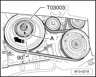
The crankshaft adapter (T03003) can only be installed correctly in one position.
- Rotate the crankshaft in engine rotation direction - arrow - far enough until the arrow - A - on the crankshaft adapter (T03003) points downward vertically, relative to the engine axis.
This position corresponds approximately to Top Dead Center (TDC) of the crankshaft for cylinder 5.
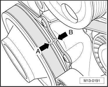
• With the engine removed, the TDC mark can be seen on the vibration damper and the belt pulley side sealing flange. Notches - A and B - must align.
- Remove the plug - 1 - from the rear of the cylinder block.
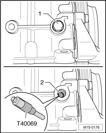
- Look through the threaded hole. Make sure the hole - 2 - in the crankshaft is lined up wit the threaded hole.
Use a mirror for this.
- Rotate the crankshaft slightly, if necessary.
- When the holes line up, install the locking pin (T40069) all the way into the threaded hole and tighten it to 10 Nm.
• With the engine removed, the TDC mark can be seen on the vibration damper and the belt pulley side sealing flange. Notches - A and B - must align.
- Make sure the crankshaft cannot be turned.
After Removal and Installation Work
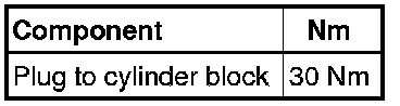
- Remove the locking pin (T40069) and install the plug - 1 - to the cylinder block.
The rest of the installation follows the reverse of the removal procedure.
Tightening Specifications
to Check/Adjust Valve Timing
- Remove the cylinder head cover. Refer to => [ Cylinder Head Cover ] Cylinder Head Cover.
- Perform the steps in "Crankshaft, Locking". Refer to => [ Crankshaft, Locking ] Procedures.
• If the camshaft threaded holes - arrows - do not point upward, the crankshaft must be rotated one rotation (360°) in engine rotation direction.
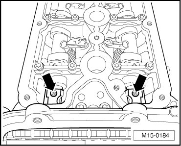
In order to be able to precisely check and adjust the valve timing, always note the following:
• Rotate the crankshaft only in engine rotation direction - arrow -. Do not rotate the crankshaft back.
• The crankshaft should not be rotated past the Top Dead Center (TDC) mark. This means the bore - 2 - in the crankshaft must not be above the threaded opening in the cylinder block.
If the crankshaft was rotated past the TDC mark:
- Then, rotate the crankshaft back 45° opposite the engine rotation direction.
- Then, rotate the crankshaft forward again in engine rotation direction to the TDC position.
When the crankshaft is positioned slightly in front of the TDC position (hole in crankshaft is 90% visible), the locking pin (T40069) can be installed, although slightly more difficult.