Procedures
Shift Mechanism Function Unit, Manual Release Assembly Overview
• Lubricate bearing areas and slide surfaces with polycarbamide grease (G 052 142 A2).
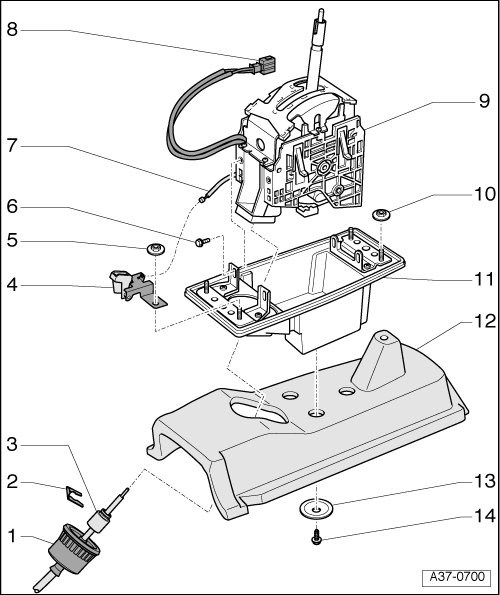
1 Selector lever cable rubber boot
• Check whether selector lever cable rubber boot is engaged correctly on shift mechanism shift unit and sealed well
• In case of damaged rubber boot, selector lever cable must be replaced
2 Locking clip
• For selector lever cable to shift mechanism function unit
• Installation position: Angled end faced upward
3 Selector lever cable
• => [ Selector Lever Cable Assembly Overview ] Selector Lever Cable Overview
4 Bracket
• With rocker switch for manual release
5 Nut
• 8 Nm
6 Bolt
• 3.5 Nm
7 Manual release actuator cable
• Removing and installing => [ Actuator Mechanism for Manual Release, Removing and Installing ] Removal and Replacement
8 Electrical connector
• For Shift Lock Solenoid (N110) and Transmission Park Selector Switch (F305)
9 Selector mechanism function unit
• With Shift Lock Solenoid (N110) and Transmission Park Selector Switch (F305)
• Can only be replaced as complete unit
• Removing and installing => [ Shift Mechanism with Selector Lever Cable, Removing and Installing ]
10 Nut
• 8 Nm
11 Selector mechanism shift unit
• With bonded-on gasket
12 Noise insulation
13 Lock washer
• For noise insulation to shift mechanism
• Replace
14 Bolt
• 1.5 Nm
Shift Mechanism Function Unit, Removing and Installing
Special tools, testers and auxiliary items required
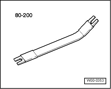
• Pry lever (80 - 200)
Removing
- Place selector lever in position "D".
- With ignition switched off, disconnect battery Ground (GND) cable.
- Remove selector lever handle => [ Selector Lever Handle, Removing and Installing ] Selector Lever Handle and Shift Mechanism Cover Overview.
- Remove front ashtray
- Remove center console trim.
- Pull electrical connector - 1 - out of protective sleeve - 2 -.
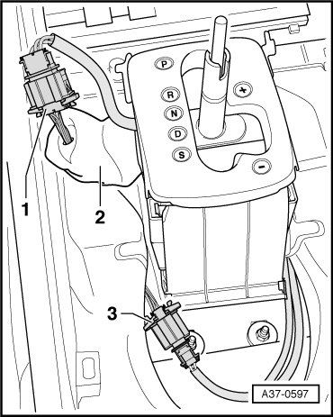
- Disconnect electrical connector - 1 - for circuit board.
- Disconnect electrical connector - 3 - for Shift Lock Solenoid (N110).
• Connector - 3 - is also covered by a protective sleeve.
- To disconnect cover from shift mechanism function unit, carefully release retaining tabs - arrows - one after another.
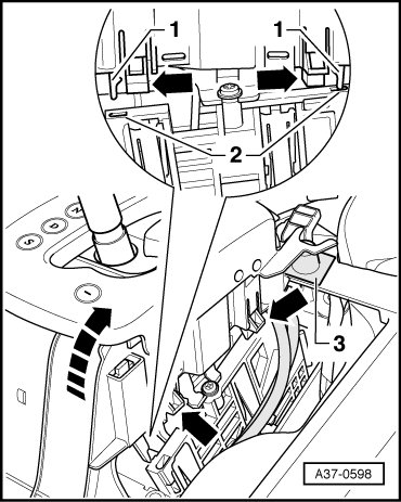
- Pull cover upward slightly until cover guides - 1 - outside of openings - 2 -.
- Then lift rear of cover upward in direction of - arrow - and at the same time pull it over cross member of center console - 3 -.
- Remove shield from selector shaft lever.
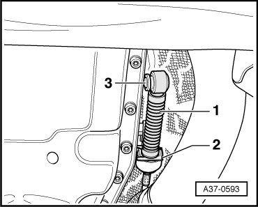
- Press selector lever cable ball socket - 1 - off selector shaft lever - 3 - using Pry Lever (80 - 200).
- Remove locking clip- 2 - on support bracket for selector lever cable and remove selector lever cable.
- Pry bowden cable - 1 - for manual release out from bracket - 2 -.
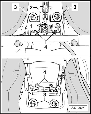
- Loosen nuts - 3 - approx. one turn.
- Remove bolts - 4 -.
- Carefully pull shift mechanism function unit up slightly out of shift mechanism cover.
- At the same time, guide out actuator mechanism for manual release - A - and selector lever cable - B - from cover.
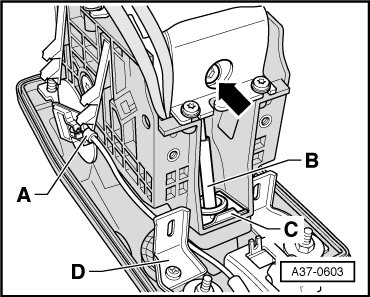
• If necessary, unclip rubber sleeve for selector lever cable from cover.
- Loosen selector lever cable locking screw - arrow - with Torx 25 socket.
- Remove selector lever cable to shift mechanism function unit locking clip - C - forward.
- Remove shift mechanism function unit. Remove selector lever cable at the same time without bending it.
Installing
Installation is in reverse order of removal. Note the following:
Torque specifications for bolts and nuts, and whether bolts and nuts are to be replaced, refer to => [ Shift Mechanism Function Unit, Manual Release Assembly Overview ] Procedures.
• Shift selector lever and selector shaft lever in "D" position.
- Guide selector lever cable - B - into shift mechanism function unit and selector lever cable locking screw hole - arrow -,
- Install selector lever cable to shift mechanism function unit locking clip- C -.
• Installation position: The angled end of the locking clip faces upward.
- If necessary, attach rubber sleeve for selector lever cable - B - to shift mechanism cover.
- Verify that rubber sleeve for selector lever cable is properly attached to shift mechanism shift unit and seals properly.
- Carefully guide shift mechanism function unit into shift mechanism shift unit, noting manual release actuator - A -.
• The Bowden cable must be routed beneath the right mounting bracket - D -.
- Guide cover over selector lever - 4 - and at the same time under cross member for center console - 3 - at front.
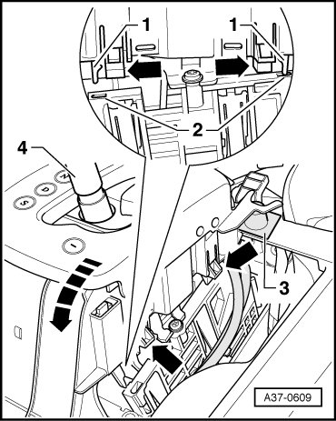
- Then pivot cover downward at rear in direction of - arrow -.
- Insert cover guides - 1 - in opening - 2 -.
- Then push down on cover until retainer tabs - arrows - clip into place.
- Carefully insert selector lever cable in support bracket/transmission and press on to lever/selector shaft. Do not bend lever/selector shaft when doing this, otherwise shifting can no longer be adjusted precisely.
- Adjust selector lever cable => [ Selector Lever Cable, Checking and Adjusting ] Selector Lever Cable Overview.
- Install ashtray and center console cover panel.
- Connect ground cable to battery
- Check shift mechanism => [ Selector Mechanism, Checking ] Selector Mechanism Overview.
Shift Mechanism with Selector Lever Cable, Removing and Installing
• If repair work only needs to be done on the shift mechanism function unit, it can be removed and installed separately => [ Shift Mechanism Function Unit, Removing and Installing ].
Special tools, testers and auxiliary items required
• Pry lever (80 - 200)
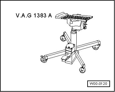
• Engine/Transmission Jack (V.A.G 1383 A)
Removing
- Place selector lever in position "D".
- With ignition switched off, disconnect battery Ground (GND) cable.
- Remove selector lever handle => [ Selector Lever Handle, Removing and Installing ] Selector Lever Handle and Shift Mechanism Cover Overview.
- Remove front ashtray.
- Remove center console cover panel.
- Pull electrical connector - 1 - out of protective sleeve - 2 -.
- Disconnect electrical connector - 1 - for circuit board.
- Disconnect electrical connector - 3 - for Shift Lock Solenoid.
• The connector - 3 - is also covered by a protective sleeve.
- To disconnect cover from shift mechanism function unit, carefully release retaining tabs - arrows - one after another.
- Pull cover upward slightly until cover guides - 1 - outside of openings - 2 - on shift mechanism function unit.
- Then lift rear of cover upward direction of - arrow - and at the same time pull it over cross member of center console - 3 -.
- Remove nuts - arrows -.
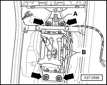
- Remove bracket - A - for manual release mechanism from studs.
- Press 4 bracket - B - for shift mechanism function unit and secure it, e.g. with wire.
- Raise vehicle.
- Remove cross member - A - below exhaust system.
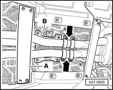
- Separate front exhaust pipes with catalytic converter from rear exhaust system - arrows - and tie them up to side.
- Remove shield - B -.
- Remove air duct - 1 - from transmission.
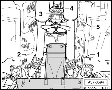
- Remove noise insulation - 2 - below transmission.
- Remove heat shield - 3 - for drive shaft.
- Remove drive shaft - 4 - at transmission and tie up or support.
- Remove heat shield - 5 - above drive shaft and push toward rear.
Lower back of transmission:
CAUTION!
For the following steps, note:
Do not support on transmission oil pan - risk of damage.
- Insert a bolt M12x100 - 1 - with attached nut - 2 - in mount behind transmission oil pan.
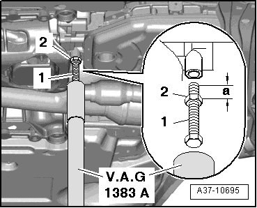
• Dimension - a - = 13 mm.
- Position Engine/Transmission Jack (V.A.G 1383 A) plunger on bolt head and slightly raise transmission, as shown in illustration.
- Remove bracket for noise insulation below ATF cooler.
- Mark installed position of transmission tunnel cross member on body.
- Remove left - 1 - and right - 2 - transmission bolts on tunnel cross member.
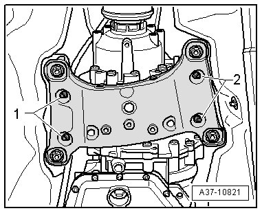
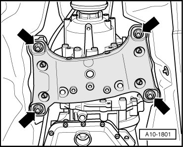
- Remove transmission tunnel cross member from body - arrows -.
CAUTION!
To prevent damage from occurring, it is very important to pay attention to everything in the engine compartment.
- Carefully lower rear of engine and transmission with Engine/Transmission Jack (V.A.G 1383 A).
- The front exhaust pipes should not contact subframe.
- Remove shield from selector shaft lever.
- Press selector lever cable ball socket - 1 - off selector shaft lever - 3 - using Pry Lever (80 - 200).
- Remove locking clip - 2 - on support bracket for selector lever cable and remove selector lever cable.
- Pry off retaining washers - arrows - for noise insulation - 2 - from cover for shift mechanism.
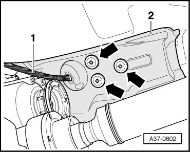
- If equipped, remove bolt for noise insulation.
- Guide noise insulation - 2 - over selector lever cable - 1 - and out.
- Remove shift mechanism and selector lever cable downward.
Installing
Installation is in reverse order of removal. Note the following:
Torque specifications for bolts and nuts, and whether bolts and nuts are to be replaced, refer to => [ Shift Mechanism Function Unit, Manual Release Assembly Overview ] Procedures.
• Shift selector lever and selector shaft lever in "D" position.
- Raise vehicle.
- Install shift mechanism function unit on body.
• When inserting, the 4 braces serve as protection to prevent the shift mechanism function unit from falling out.
• If one or more braces break off, remove them. The shift mechanism function unit does not have to be replaced because of this.
- Guide noise insulation - 2 - over selector lever cable - 1 - on shift mechanism cover.
- Install new lock washers - arrows -.
- If equipped, install bolt for noise insulation to 2 Nm.
- Route selector lever cable - 1 - above securing points - arrows - for tunnel cross member - 2 -.
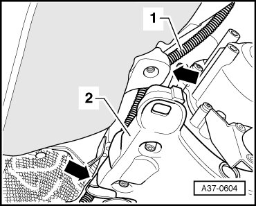
• Do not bend or kink the selector lever cable.
- Place selector lever cable - 1 - into support bracket/transmission and carefully press cable onto selector shaft lever - 3 -. Do not bend lever/selector shaft when doing this, otherwise shifting can no longer be adjusted precisely.
- Press new locking clip - 2 - onto selector lever cable at support bracket/transmission.
• Installation position: The angled end of the locking clip must point toward the end of selector lever cable.
- Attach shield to selector shaft lever.
- Carefully raise engine and transmission at rear making sure not to pinch selector lever cable.
• When installing tunnel cross member on body, observe installation position (markings from removal).
- Install tunnel cross member => [ Tunnel Crossmember ] Front Transmission Support and Transmission Mount.
- Attach drive shaft to transmission flange 01R
- Reconnect front exhaust pipes to rear exhaust system.
- Set bracket - A - for manual release mechanism onto studs.
- Tighten nuts - arrows -.
- Guide cover over selector lever - 4 - and at the same time under cross member for center console - 3 - at front.
- Then pivot cover downward at rear in direction of - arrow -.
- Insert cover guides - 1 - in openings - 2 -.
- Then push down on cover until retainer tabs - arrows - clip into place.
- Connect electrical connector - 3 - for Shift Lock Solenoid (N110).
- Push connector - 3 - into protective sleeve (not shown in illustration).
- Connect electrical connector - 1 - for circuit board.
- Push electrical connector - 1 - out of protective sleeve - 2 -.
- Adjust selector lever cable => [ Selector Lever Cable, Checking and Adjusting ] Selector Lever Cable Overview.
- Install ashtray and center console trim.
- Install selector lever handle => [ Selector Lever Handle, Removing and Installing ] Selector Lever Handle and Shift Mechanism Cover Overview.
- Connect Ground (GND) cable to battery =>.
- Check shift mechanism => [ Selector Mechanism, Checking ] Selector Mechanism Overview.
Actuator Mechanism for Manual Release, Removing and Installing
Removing
• Shift mechanism function unit removed.
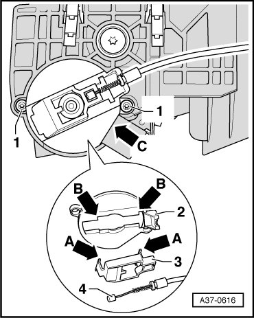
- Remove bolts - 1 - and remove actuator mechanism.
Installing
- To assemble actuator mechanism, insert sliding bracket - 3 - with tabs - arrows A - into cut-outs - arrows B - of cover - 2 -.
- Clip end of Bowden cable - 4 - into sliding bracket and bracket into cover.
- Secure assembled actuator mechanism to shift mechanism function unit.
• Flat part - arrow C - faces toward connecting wires.
Bolt tightening torque - 1 -: => [ Selector Mechanism Assembly Overview ] Selector Mechanism Overview