Fuel Injection System
The control function #2 will allow you to test one or several input devices with help of the diagnostic socket.The Bosch LH-2.4 Jetronic fuel injection system can check the throttle position, crankshaft position/speed, A/C pressure, A/C switch and gear selector sensor signal. For information on the three different control functions or how to operate the diagnostic socket, see ON-BOARD DIAGNOSTICS under TESTING PROCEDURES.
Diagnostic Socket Pin #2:
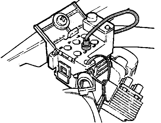
TESTING PROCEDURE:
1. Turn ignition ON.
2. Open the diagnostic socket cover and connect the selector cable to pin #2.
Turning Throttle:
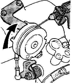
3. Turn throttle to full load position.
Entering Control Function #2:
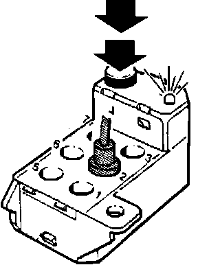
4. Depress the button on the diagnostic socket twice.
Each time depress the button for at least 1 second but not more than 3 seconds.
5. The light diode should begin to flash.
Code 3-3-3:
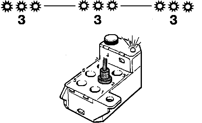
6. Release throttle control.
7. If the code 3-3-3 flashes, the throttle position sensor is operating correctly in the full load position.
a. If light diode continues to flash rapidly, see THROTTLE POSITION SENSOR under COMPONENT TESTING.
b. If light diode doesn't work at all, see DIAGNOSTIC SOCKET under COMPONENT TESTING.
Code 3-3-2:
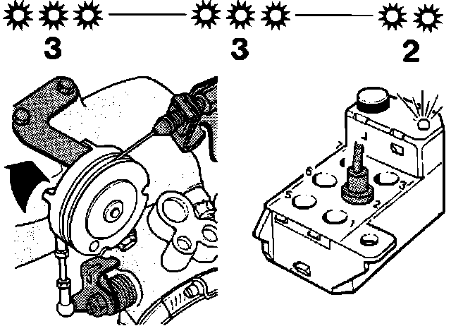
8. Open the throttle slightly (idle switch opens), light diode should turn off and start flashing code 3-3-2.
a. If so, throttle position sensor idle switch is O.K..
b. If light diode continues to flash rapidly, see THROTTLE POSITION SENSOR under COMPONENT TESTING.
Code 3-3-1:

9. Check the crankshaft position/speed signal. Start engine, if not possible, see step 11.
10. If the light diode turns off and then flashes code 3-3-1, crankshaft position/speed signal is working correctly.
If diode flashes rapidly, see step 12.
11. If engine won't start, crank starter until the light diode turns off.
12. If diode continues to flash rapidly, ignition system must be checked, see ON-BOARD DIAGNOSTICS under TESTING PROCEDURES. If ignition system is fault free, see step 20 and in addition check the following components:
^ Diagnostic socket
^ Ignition switch
^ Fuel injection ECU
^ Oxygen sensor (lambda sond)
^ Throttle position sensor
^ Air mass meter
^ [1][2]System relay
These testing procedures can be found in COMPONENT TESTING under TESTING PROCEDURES.
Code 1-1-4:

13. Check A/C compressor operation (if vehicle is not equipped with A/C, proceed with step 20).
Turn air conditioning ON.
14. If the light diode turns off and then flashes code 1-1-4, the A/C switch is O.K..
15. If diode continues to flash rapidly, check A/C switch (see Powertrain Management/Computers and Control Systems/Testing and Inspection/Procedures under COMPONENT TESTING).
16. The light diode will now return to rapid flashes, before the A/C compressor turns on.
Code 1-3-4:

17. When the compressor turns on, the light diode turns off and then starts flashing code 1-3-4.
18. If diode continues to flash rapidly, check A/C pressure sensor wiring to fuel injection ECU (green wire, pin 14 at ECU connector).
19. Turn engine off.
Code 1-2-4:

20. Testing idle speed compensation (vehicles with automatic transmission only). If vehicle is equipped with manual transmission, proceed to step 26.
21. Start engine.
22. Depress the brake pedal.
23. Place the gear selector in drive (D) and then back to the neutral (N) position. The light diode should flash code 1-2-4.
24. If diode continues to flash rapidly, check gear selector (inhibitor) switch (see GEAR SELECTOR (INHIBITOR) SWITCH under COMPONENT TESTING).
25. Turn engine off.
26. Remove selector cable and close the diagnostic socket.