Fuel Injection System
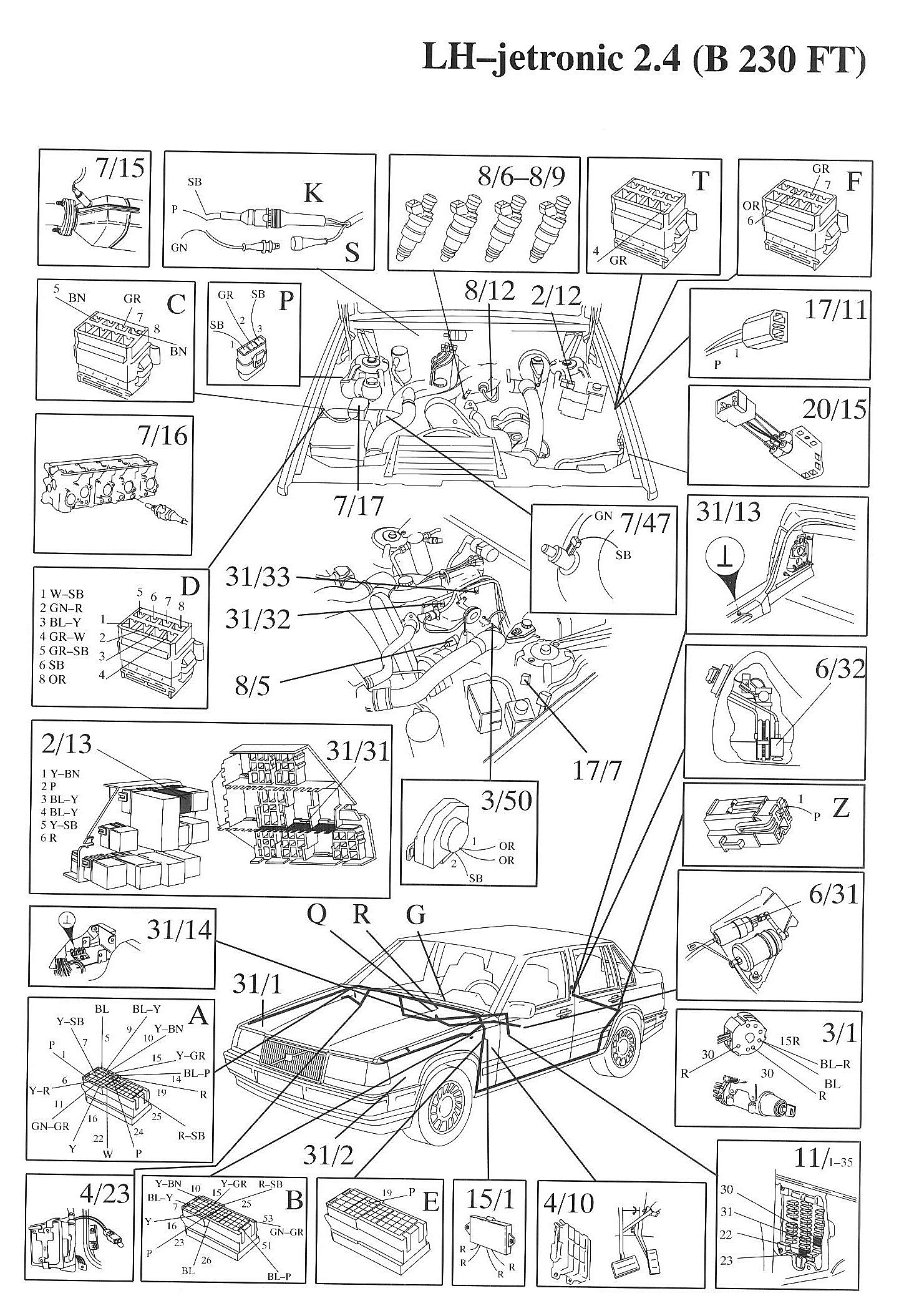
Component / Connector Views:
Wiring Diagrams:
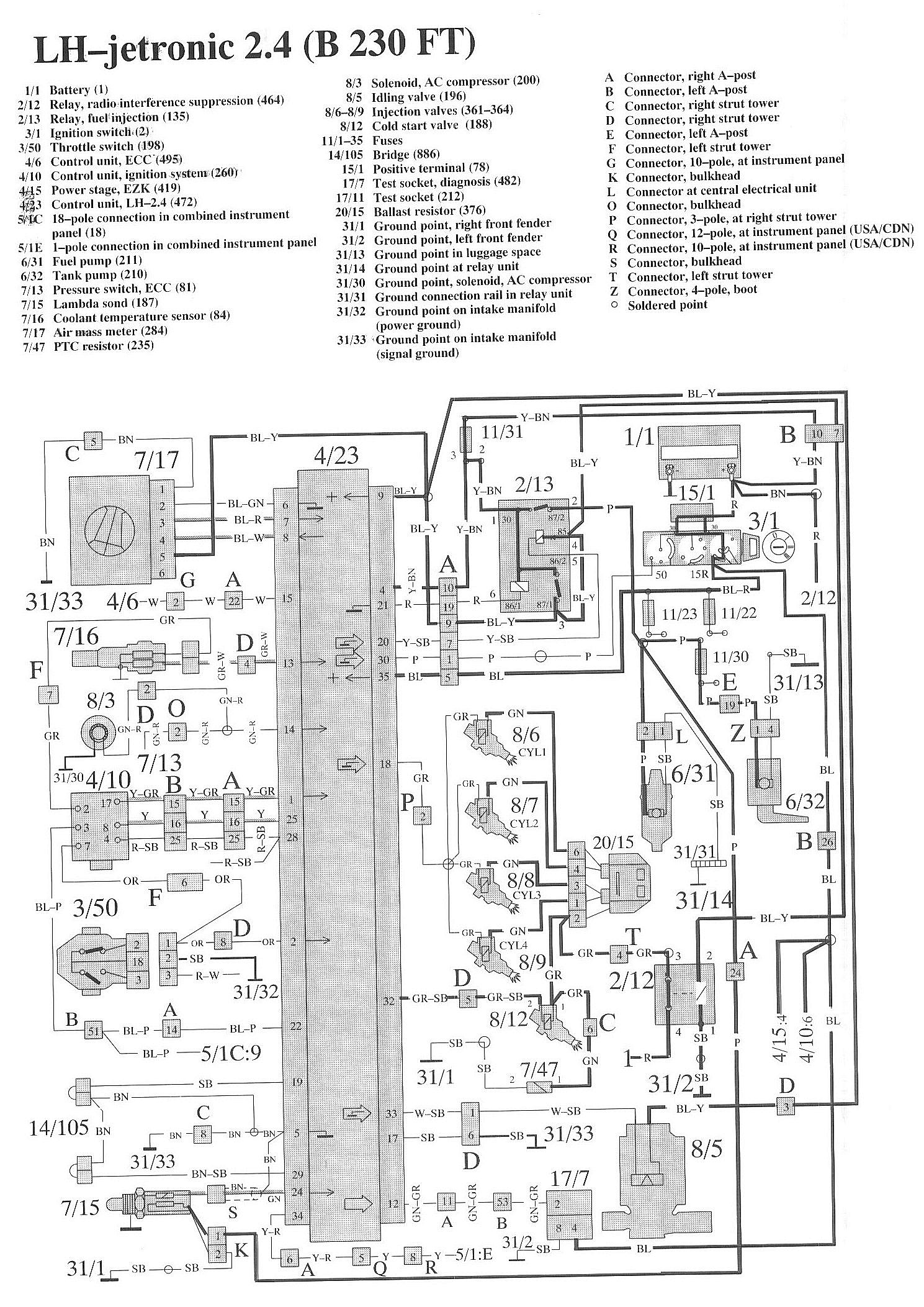
LEGEND
1/1 Battery
2/12 Relay, radio interference suppression
2/13 Relay, fuel injection
3/1 Ignition switch
3/50 Throttle switch
4/6 Control unit, ECC
4/10 Control unit, ignition system
4/15 Power stage. EZK
4/23 Control unit. LH-2.4
5/1C 18-pole connection in combined instrument panel
5/1E 1-pole connection in combined instrument panel
6/31 Fuel pump
6/32 Tank pump
7/13 Pressure switch, ECC
7/15 lambda sond
7/16 Coolant temperature sensor
7/17 Air mass meter
7/47 PTC resistor
8/3 Solenoid, AC compressor
8/5 Idling valve
8/6-8/9 Injection valves
8/12 Cold start valve
11/1-35 Fuses
14/105 Bridge
15/1 Positive terminal
17/7 Test socket, diagnosis
17/11 Test socket
20/15 Ballast resistor
31/1 Ground point, right front fender
31/2 Ground point. left front fender
31/13 Ground point in luggage space
31/14 Ground point at relay unit
31/30 Ground point, solenoid, AC compressor
31/31 Ground connection rail in relay unit
31/32 Ground point on intake manifold (power ground)
31/33 Ground point on intake manifold (signal ground)
A Connector, right A-post
B Connector, left A-post
C Connector, right strut tower
D Connector, right strut tower
E Connector, left A-post
F Connector, left strut tower
G Connector, 10-pole, at instrument panel
K Connector, bulkhead
L Connector at central electrical unit
O Connector, bulkhead
P Connector, 3-pole, at right strut tower
Q Connector, 12-pole, at instrument panel (USA/CDN)
R Connector, 10-pole, at instrument panel (USA/CDN)
S Connector, bulkhead
T Connector, left strut tower
Z Connector, 4-pole, boot