Cruise Control - Installation
87volvo04SECTION GROUP NO.
27 109
DATE NOVEMBER 1987
RE:
INSTALLATION OF CRUISE CONTROL
740
THIS BULLETIN APPLIES TO THE U.S. AND CANADA
REFERENCE: PARTS ACCESSORY BULLETIN, GRP: COMFORT, #1A, NOV. '87
Installation of Cruise Control on 1988 M/Y 740
Changes on the cable harness for 1988 M/Y 740 requires that some modifications be performed when installing cruise control. The new cable harness will be installed in production from week 748.
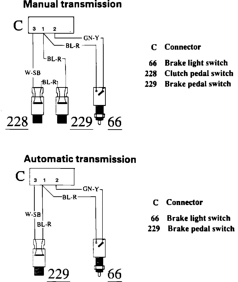
AUTOMATIC TRANSMISSIONS
1. Remove the existing cable harness (P/N 1363174-2) connected between the instrument panel cable harness, and the brake light switch.
NOTE: ALWAYS DISCONNECT HOLDING THE INSULATOR, NOT THE LEADS.
2. Install in its place the new cable harness (P/N 1362930-8).
3. Connect the two terminal connector (W-SB, BL-R) coming from this new harness, to the brake pedal vacuum switch.
4. Connect the remaining single terminal connectors (BL-R, GN-Y) to the brake light switch.
MANUAL GEARBOXES
1. Disconnect cable harness (P/N 1362930-8) from the instrument panel cable harness.
NOTE: ALWAYS DISCONNECT HOLDING THE INSULATOR, NOT THE LEADS.
2. Disconnect the BL-R cable from the two terminal connector.
3. Connect the cable harness (P/N 1323359-8) which is supplied with the cruise control kit, into the two terminal connector from which the BL-R lead was removed in step 2.
4. Connect the BL-R lead removed in step 2, to the open position on the connector (P/N 1323359-8) installed in step 3.
NOTE: BE SURE TO BEND THE LOCKING PIN ON THIS TERMINAL TO INSURE IT IS LOCKED INTO THE CONNECTOR WHEN REINSTALLED.
5. Reconnect this harness assembly to the instrument panel cable harness.
6. Attach the 2 terminal connector (W-SB, BL-R) to the clutch pedal vacuum switch.
7. Attach the 2 terminal connector (BL-R, BL-R) to the brake pedal vacuum switch.
8. Attach the remaining single terminal connectors (BL-R, GN-Y) to the brake light switch.
All other aspects of the cruise installation will remain unchanged from the instructions provided in each kit.