Engine - Cold Start Condition
Model:700
Group:
23
Number:
708
Title:
Cold Start Condition
1985-87 B230F Automatics Only
1985-89 B230FT Automatics Only
Market:
US and Canada
Date: January 1994
THIS BULLETIN SUPERSEDES SB 223-708; 4/89
Reference:
TP 31140/2 (English); 3/87; B230F 740 1985-
TP 31451/1 (English); 6/89; B230FT Engine 700 1985-19..
Cold Start Condition - B230F/FT Automatics Only
This information only pertains to B230F/FT automatics as follows:
B230F automatics with LH MFI control module:
Volvo P/N 1389094-2
Bosch P/N 0 280000 544
Volvo P/N 1336801-4
Bosch P/N 0280000511
B230FT automatics with LH MFI control module:
Volvo P/N 1367487-4
Bosch P/N 0 280000 541
Volvo P/N 1346783-2
Bosch P/N 0 280000 518
CONDITION:
The engine starts normally at approximately 68°F (20°C), but may stall immediately after starting if it is subject to load (transmission in Drive, A/C compressor and/or power steering pump on).
If all proper vehicle maintenance has been performed, and this condition still occurs, then a service kit (p/n 3531106-7) can be installed to alleviate this condition. This kit increases the engine coolant temperature sensor NTC (Negative Temperature Coefficient) voltage by 0.5 V (at 59°F, 15°C) if the engine temperature is between 41-86°F (5-30°C) when it is started. This causes the LH MFI control module to sense coolant temperature to be approximately 18°F (10°C) lower than it actually is, resulting in an increased choke factor.
The voltage is not increased until the oil pressure has risen to the point where the oil pressure sensor breaks the ground connection.
If the engine temperature is under 41°F (5°C) when it is started and enters the range 41-86°F (5-30°C) within 1 minute after start, the increased choke factor will be in effect for the remainder of that minute.
The following leads are connected to the kit's control module:
Blue-yellow (BL-Y)
Grey (GR)
Short black (SB)
Long black (SB)
To install kit:
Remove:
- soundproofing under left and right sides of instrument panel
MFI Control Module:
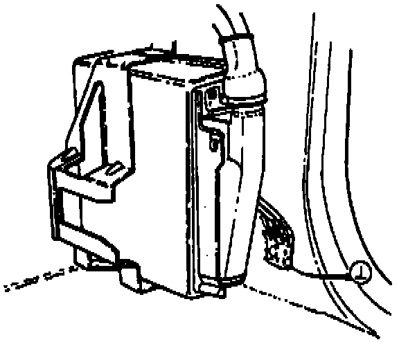
- panel on right-hand kick panel (panel covers LH MFI control module)
Note:
Check the last three digits of the Bosch part number on the control module. If the vehicle has a 554 or 591 control module, do not install the service kit. The 554 and 591 control modules already incorporate the revised programming of the kit.
Connect:
Wiring Schematic:
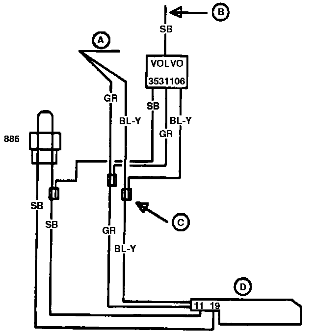
- BL-Y lead to BL-Y lead in car's wiring harness
- GR lead to GR lead in car's wiring harness
- short SB lead to one of SB leads in car's wiring harness which connects terminal 11 to terminal 19 in LH connector with bridge connector 886 (2-pole connector).
Attach service kit to wiring harness with insulating tape.
A - Car wiring harness
B - Lead to connector at left A-post
C - Scotch-lock
D - LH connector
886 - Bridge connector
Electrical Connector:
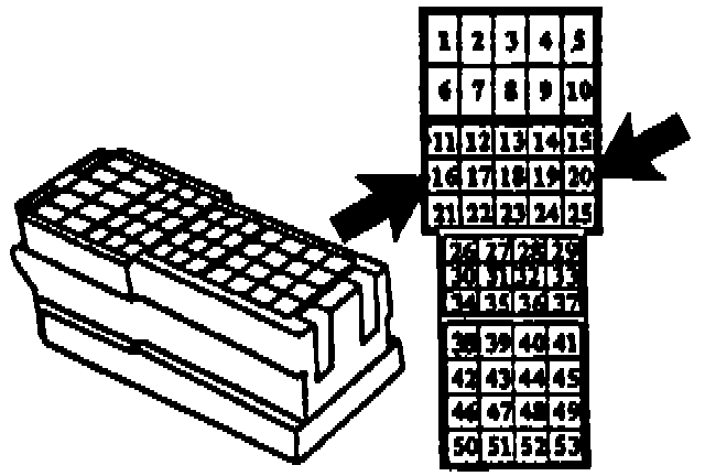
Route long SB lead under instrument panel to large connector at left A-post which connects instrument panel to left wheelhouse harness.
Connect long SB lead with Scotch-lock clamp to black wire at:
pos 16 on 740 1988/89 models
pos 20 on 760 1988/89 models
pos 16 on 740/760 1987 models
pos 16 on 780 1989 models
Electrical Connector:
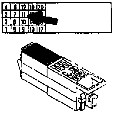
pos 11 on 740/760 1985/86 models
Reinstall cowl panel and soundproofing.

Labor/Operations Block