A/C - Procedure for Manual Control of Recirculation
85volvo01SECTION GROUP NO.
87 5
DATE JULY, 1985
RE:
P70 AC/ACC RECIRCULATION
THIS SERVICE BULLETIN IS APPLICABLE TO THE U.S. AND CANADIAN MARKETS
Some owners may be interested in closing off outside air manually to increase recirculation under certain conditions, such as driving through dust or smoke.
This Service Bulletin describes a solution which permits manual operation of the climate unit to the recirculation mode.
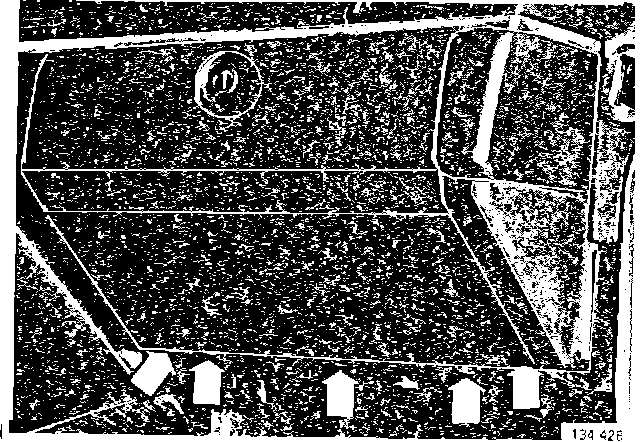
1. Disconnect the battery ground cable.
2. Remove:
- panel beneath glove compartment
- glove compartment
- wire for glove compartment mirror light (760 Only)
- panel beneath steering wheel near brake and gas pedals
- ashtray, equalizer or compartment above ashtray, whichever is equipped in vehicle
- pull out fuse box
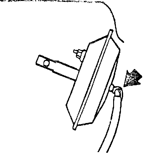
3. Disconnect the hose (orange) from the vacuum motor for the air shutter.
NOTE: The hose lock
4. Connect a new vacuum hose (300 mm) to the vacuum motor (other end of hose will be connected in Step 7)
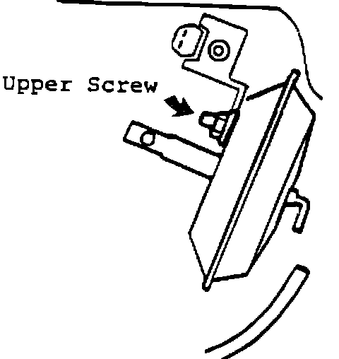
5. Install the solenoid with the upper screw for the vacuum motor. (Do not tighten nut)
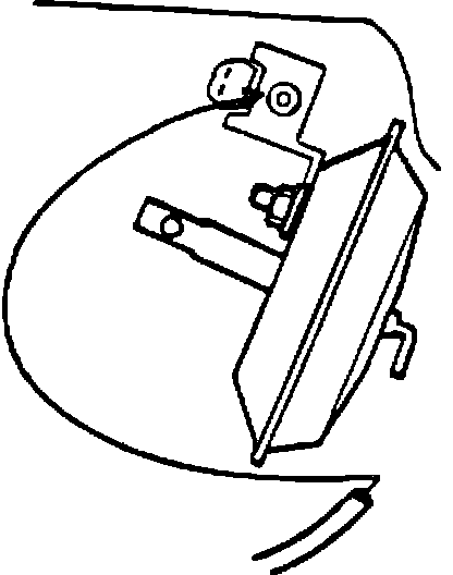
6. Connect the orange hose (previously connected to the vacuum motor) to the nipple on the solenoid, which now faces inwards towards the passenger.
(not brown or blue marked nipples.)
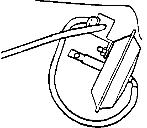
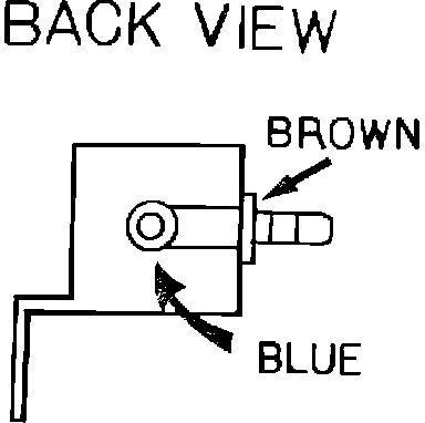
7. Connect the new hose installed in Step 4 from the vacuum motor to the outer nipple (painted brown) on the solenoid.
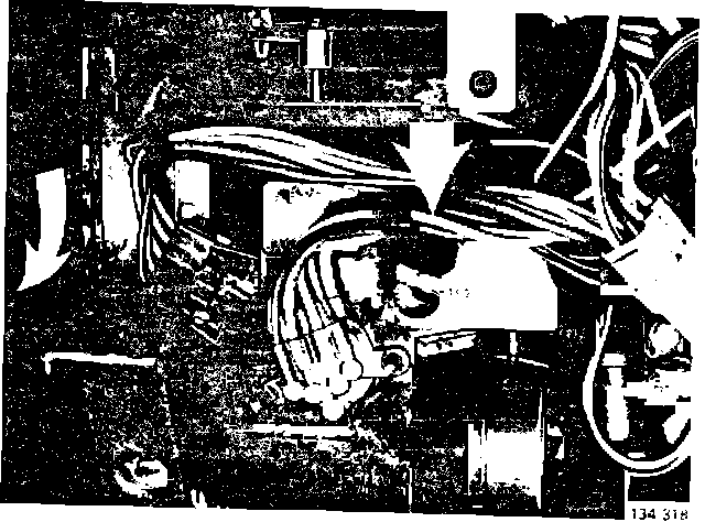
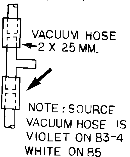
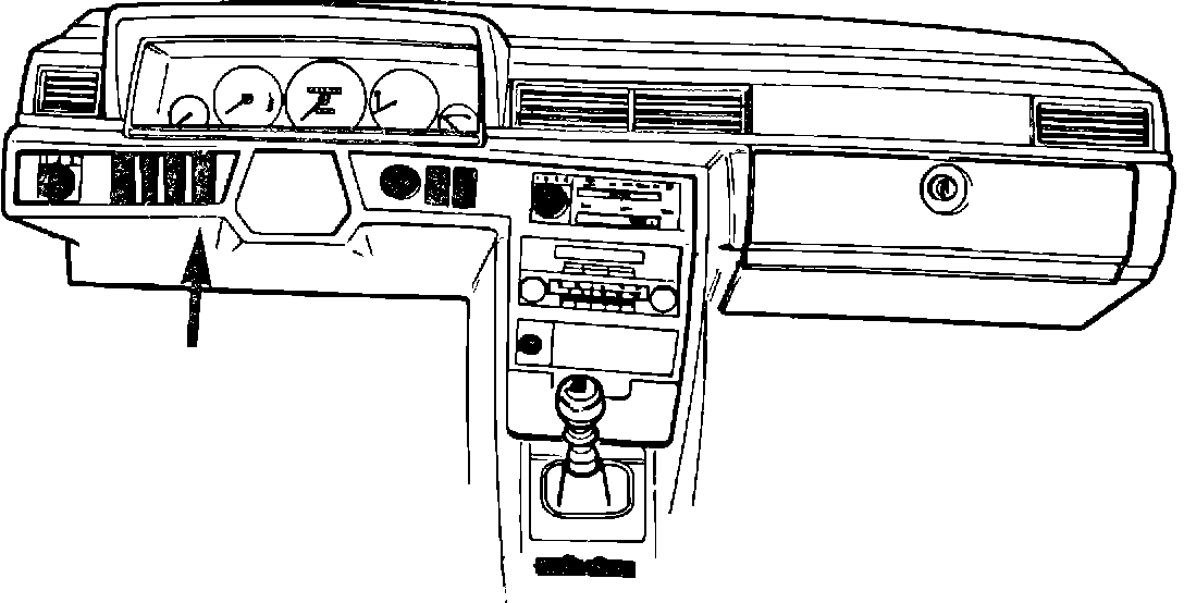
8. Using the picture to the left install the T-Nipple in the violet source vacuum hose (white on 85 MY) Location of T-Nipple:
ACC - Near Programmer (Arrow at center of picture)
Manual - in vacuum harness (in the area of the arrow to the left of the picture)
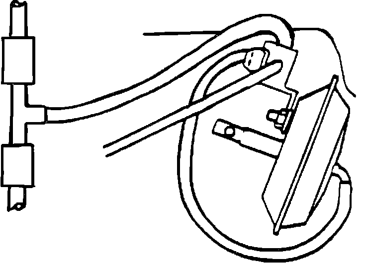
9. Connect a new hose between the T-nipple and the nipple (painted blue) on the solenoid.
10. Tighten nut holding solenoid.
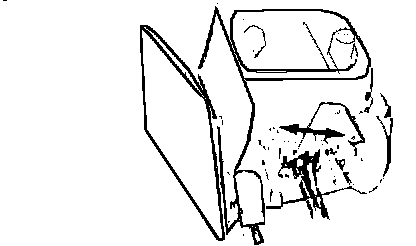
11. Remove blank plug directly to the left of the steering wheel. This will accommodate the switch after the wiring is complete.
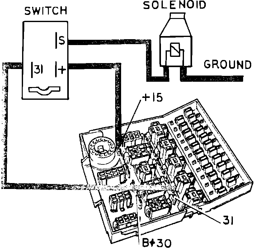
12. Construct a wiring harness according to diagram. connect +15 (fuse box) to + (switch)
- connect -31 (fuse box) to -31 (switch)
- connect S (switch) to solenoid
- connect -31 (solenoid) to the negative wire for the glove compartment light (using a scotch lock)
13. Install switch into dash.
14. Replace fuse box.
15. Reconnect the battery ground cable.
- start the engine
- check the function by observing recirculation door while operating switch
- reinstall the panels
MATERIALS REQUIRED
QUANTITY PART NO. DESCRIPTION NOTES
1 1332347-2 Solenoid
1 949024-4 T-nipple
1 1347450-7 Switch 1324008-0 (rear defrost
(marked REC) switch may also be used)
1000 mm 192055-2 Vacuum Hose 650 mm, 300 mm, and 2 x 25 mm
(39.") (25.5") (11.75) (1.")
2 1/8" wide female Terminals
Connector
5 1/4" wide female Terminals
Connector
1 Red Scotch Lock
- Purchase From Wires local supplier