Ignition System - Fault Tracing
85volvo02Reference Bulletlns: Subject: Product
SMB 34:05 HALL SWITCH
SB 37:103 REPLACEMENT AND CARS
IGNITION FAULT TRACING CHART
B21-23 B230F, P20 Group
34
Date: No.
APRIL, 1985 28
THIS BULLETIN IS APPLICABLE TO THE U.S. AND CANADIAN MARKETS
This Service Bulletin is a supplement to the Repairs and Maintenance Service Manual Section 3 (34) Ignition System 240, 260 1975-1984. TP 30432/1.
Two types of distributors are described on page 67 and 68 of the manual. They are:
1. Chrysler distributor with Chrysler connector P/N 1306059-5 MY 1982
2. Bosch distributor with Chrysler connector P/N 1332684-8 MY 1983
The distributor for MY 1984, P/N 1336737-0 and MY 1985 (B230F) P/N 1332587-3 are equipped with Bosch style connectors.
NOTE: THE DISTRIBUTOR FOR MY 1985 IS NOT INTERCHANGEABLE WITH EARLIER VERSIONS BECAUSE OF A DESIGN CHANGE TO THE TRIGGER WHEEL.
The following procedure applies to all above mentioned distributors:
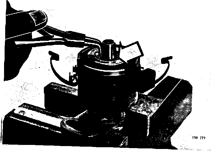
DISTRIBUTOR, RECONDITIONING
Replacement of Hall Switch
NOTE: The Hall Switch should not be replaced on distributors within the first year of warranty. The complete distributor must be replaced.
Remove distributor according to Section N5-N6 on Page 68 of Service Manual.
Mount distributor in a vice (USE SOFT VICE JAWS TO PREVENT DAMAGE)
Release circlip retaining trigger wheel
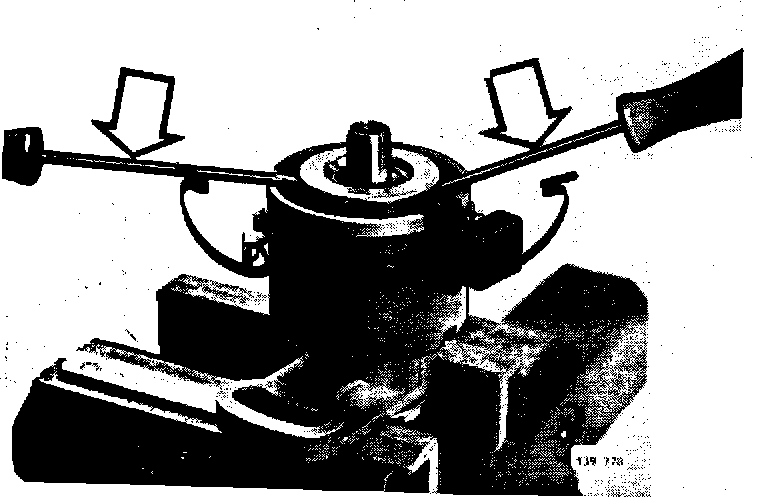
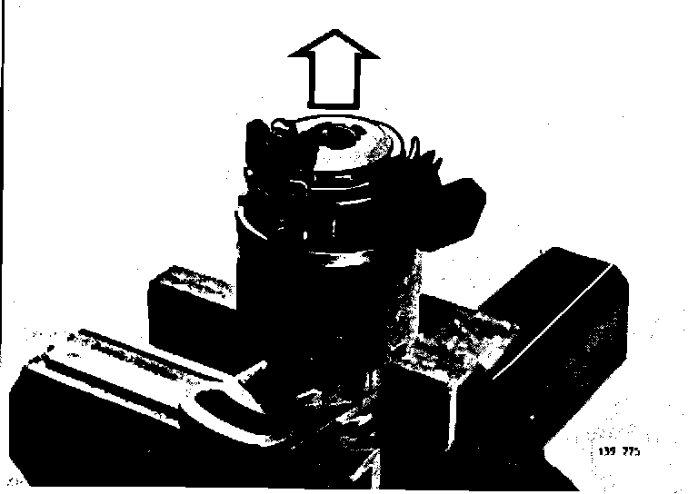
Pry off trigger wheel with two screwdrivers (use round-shaft screwdrivers, 5 mm diameter)
Place tips of screwdrivers on steel hub, as shown.
Take care not to damage trigger wheel.
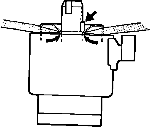
NOTE: If trigger wheel is bent during removal, it must be replaced.
Take care not to lose lock pin.
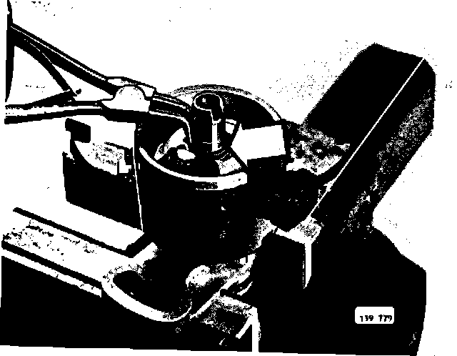
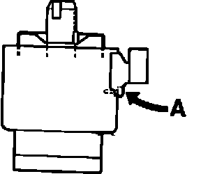
REMOVE
- circlip
- Hall pick-up retaining screws
- plastic pin (A) for connector
Remove Hall switch and connector.
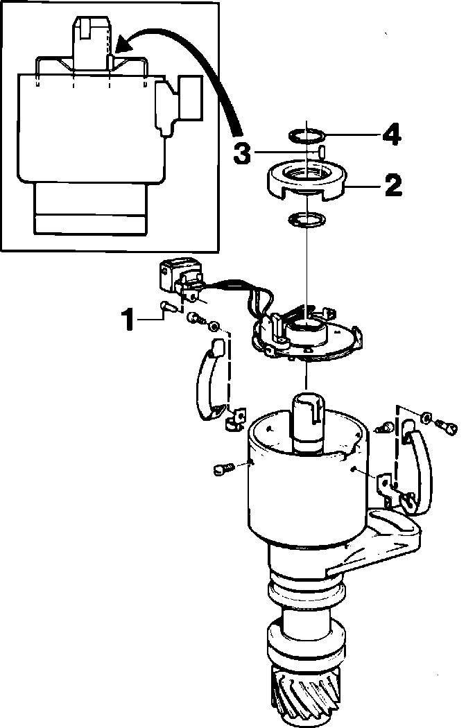
INSTALL:
- New Hall switch and connector
- circlip
- retaining screws and plastic pin (1)
INSTALL:
- trigger wheel (2)
- lockpin (3)
- circlip (4)
- condensation trap
- rotor arm
Install distributor according to N7- N8 on page 70 of Service Manual.
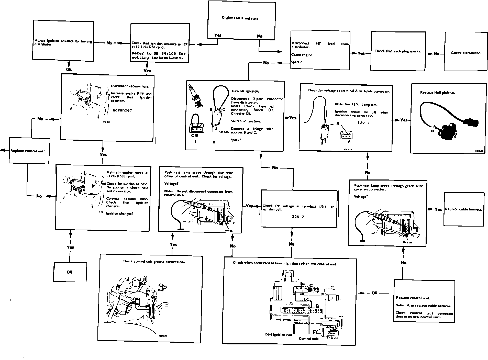
NEW FAULT TRACING CHART FOR COMPUTERIZED IGNITION SYSTEM
A revised fault tracing chart is supplied with this Bulletin. Please discard the chart at the back of Service Manual Section 3 (34) Ignition Systems 240, 260 1975-84. TP 30432/1.
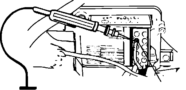
To prevent damage to connector sleeves, do not disconnect connector from control unit when checking voltage. The voltmeter should be connected directly to the wires according to the enclosed fault tracing chart.
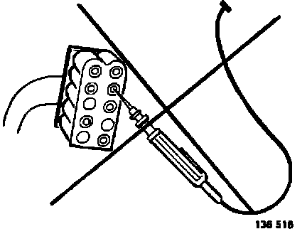
IMPORTANT!
If it is necessary to replace the control unit or disconnect the connector, the wiring harness between the distributor and the control unit MUST be replaced at the same time.
With effect from MY 1985, the guide sleeves P/N 1324909-9 are installed at pin 3, 5 and 9 in the control unit during assembly.
The guide sleeves on earlier control units should be checked and installed if missing at 3, 5 and 9. Refer to Service Manual TP 30432/1.