New Blower Housing, Modification For Original Motor
NOTE: When replacing the blower housing with the new type ( Part Number 3537209-3 ) and using the original blower motor, the new blower housing must be modified to suit the motor. The following procedure describes the removal of the original and the modification of the new blower housing. This is followed by the procedure for installing the new housing.Modification Of New Blower Housing:
1. Disconnect battery ground lead.
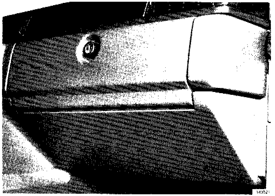
2. Remove:
- panel under glove box
- glove box
- sill moulding.
3. Remove panel over control module.
NOTE: Take care to avoid damaging panel.
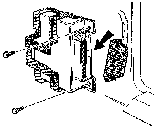
4. Disconnect connector from control module.
5. Remove:
- control module mounting screws
- control module
- control module bracket.
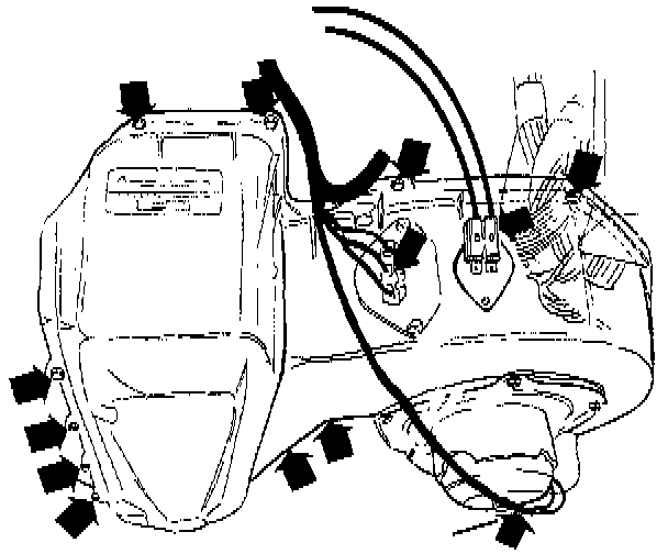
6. Remove from original blower housing:
- electrical terminals for blower motor and resistors
- screws securing lower blower housing.
NOTE: Two of screws are concealed between blower housing and evaporator housing.
- complete blower housing
- sealant residue from heater
- connector from sensor on cars with ACC.
NOTE: Care must be taken when removing connector due to special catches on terminal pins.
7. Remove from original blower housing:
- drain pipe seal
- electrical connectors
- blower motor and cooling air hose.
8. Clean motor mating face with blower housing.
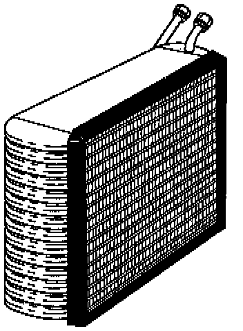
9. Inspect rubber seal to ensure it is not loose around evaporator. Clean and bond as required. Illustration shows evaporator and seal.
10. Drill, in new blower housing:
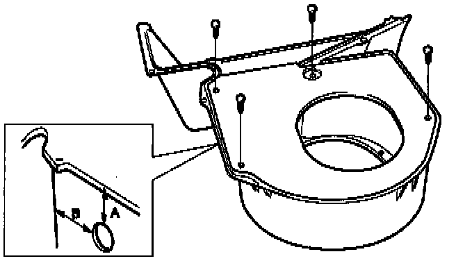
- hole for ambient air sensor in case of ACC system. Use 25 mm hole saw. Mark position of hole on original blower housing and transfer dimensions to new housing (e.g. A and B in illustration) to ensure identical position.
- two 3 mm diameter holes for mounting screws. Use Use sensor as drilling template.
11. Test-mount housing - remove plate from blower housing.
12. Remove from new blower housing:
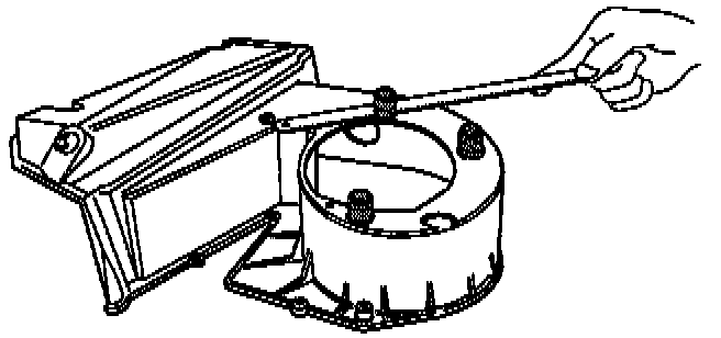
- motor locating studs (three). Use saw and cut close to housing.
- surface roughness. Use file.
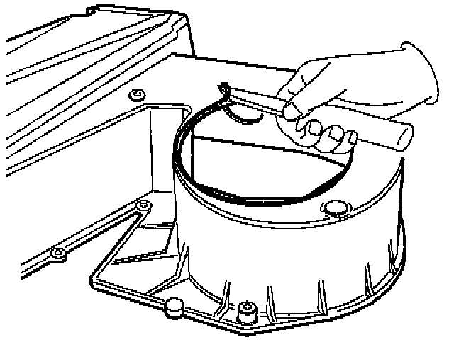
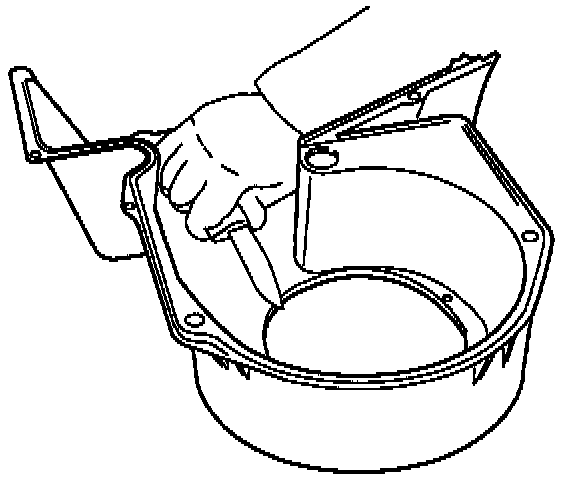
13. Use knife, to remove from new blower housing, raised edge around outside and inside of housing opening.
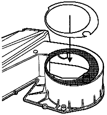
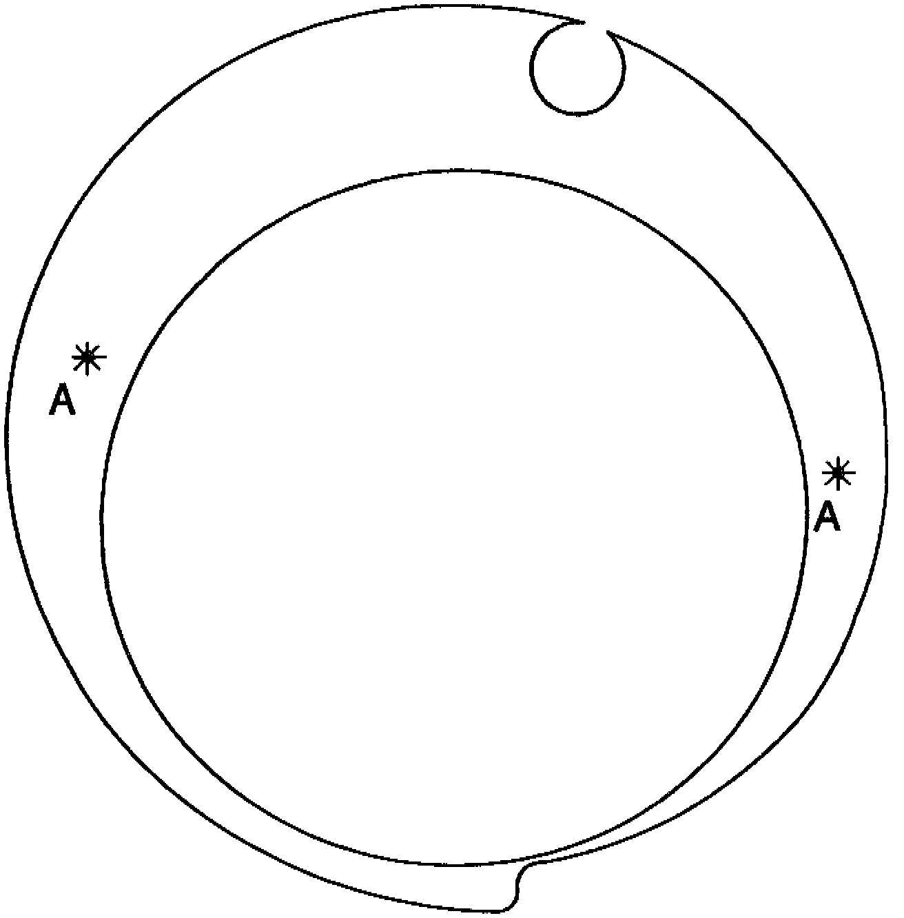
14. Take paper template and original blower housing. Template is shown on illustration. Copy and cut out template. Attach template to blower housing with edges of holes aligned. Mark cutting line on blower housing along outer edge of template (dashed line in illustration).
NOTE: Line must be marked out straight past, not around hose branch.
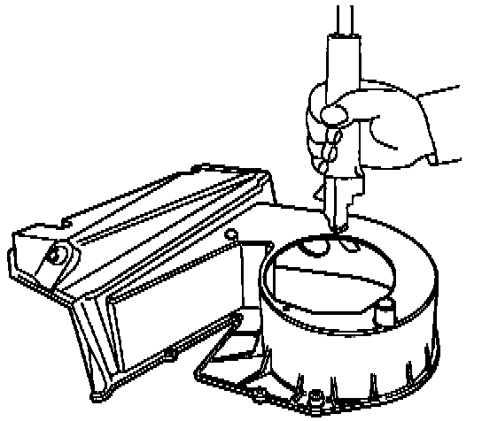
15. Remove template and cut housing. Use motorized jigsaw or hacksaw blade to cut along marked-out line.
NOTE: Cutout section is referred to as reinforcing piece in text below. Reinforcing piece must be used to reinforce motor mounting in new blower housing when original blower motor is installed.
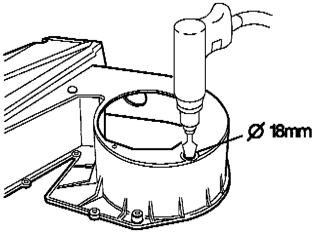
16. Enlarge hole in new blower housing. Drill out hole for blower motors cooling hose in new blower housing to 18 mm.
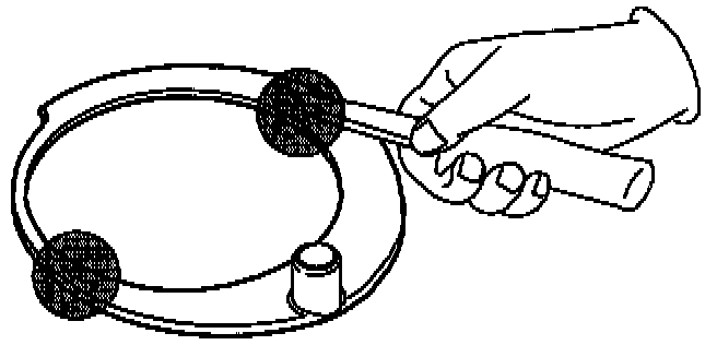
17. Remove motor locating pins (two) from rein-forcing piece with knife (shaded area in illustration).
18. Fit reinforcing piece inside new blower housing. Cooling hose branch should pass through enlarged hole without forcing. Test and adjust as required.
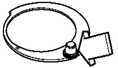
19. Seal around base of cooling hose branch with strip of butyl tape. Seal is required against moisture.
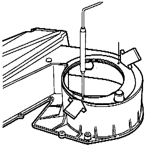
20. Drill holes for rivets:
- Position holes correctly by means of marks on template (indicated by arrows in illustration). Install reinforcing piece inside housing. Fix reinforcing piece in correct position with clips or similar means.
NOTE: Ensure that edges of openings in reinforcing piece and template are aligned with opening in new housing.
- Drill 3 mm hole for each pop rivet through template, blower housing and reinforcing piece. Fold aside template but leave fixing tools in position.
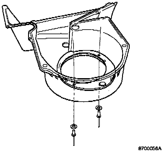
21. Install pop rivets:
- Attach reinforcing piece permanently using suitable pop rivets in drilled holes.
- Remove fixing tools and template.
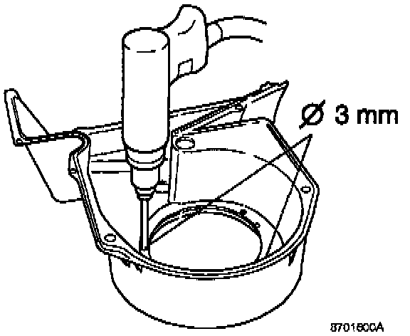
22. Drill hole through each motor locating pin from inside of housing. Use 3 mm drill.
23. Install butyl tape and blower motor. Place strip of butyl tape around motor mating face to seal against housing and install blower motor.
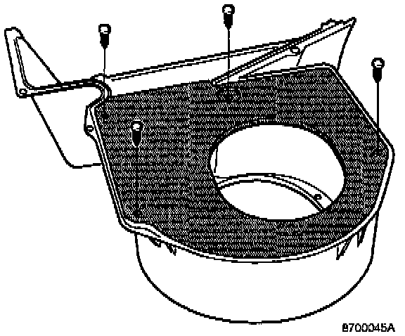
24. Install plate removed earlier and turn blower impeller. Check impeller clearance and inspect seal around housing drain pipe. Replace seal (Part Number 3522821-2) if required.
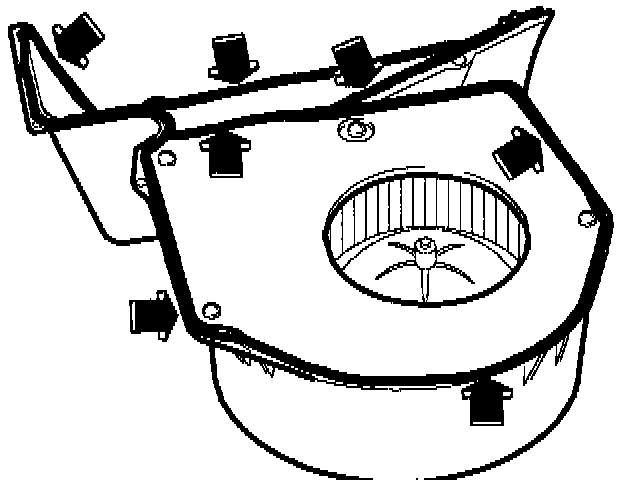
25. Place sealant in groove in lower blower housing. Sealant should fill groove completely to ensure perfect seal when blower housing is in place. Run sealant as indicated by arrows in illustration.
26. Install lower blower housing. Connect electrical leads to blower motor and blower resistors. Adjust wiring.
27. Reinstall:
- control module bracket
- control module.
28. Reconnect connector.
29. Reinstall:
- control module cover
- battery ground lead.
30. Check blower operation.
31. Reinstall:
- sill moulding
- glove box
- panel under glove box.