Standard Heater Installation
C22
Before installing, check that air intake seal is intact and correctly positioned in its seat.
C23
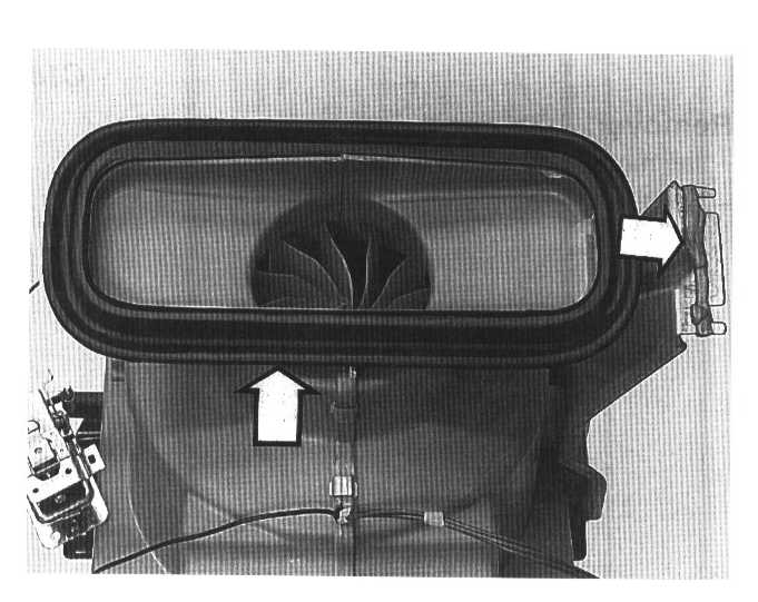
Put sealing compound around screw holes in RH mounting (as shown by arrow).
Note: When installing heater, be careful not to dislodge air intake from its position.
C24
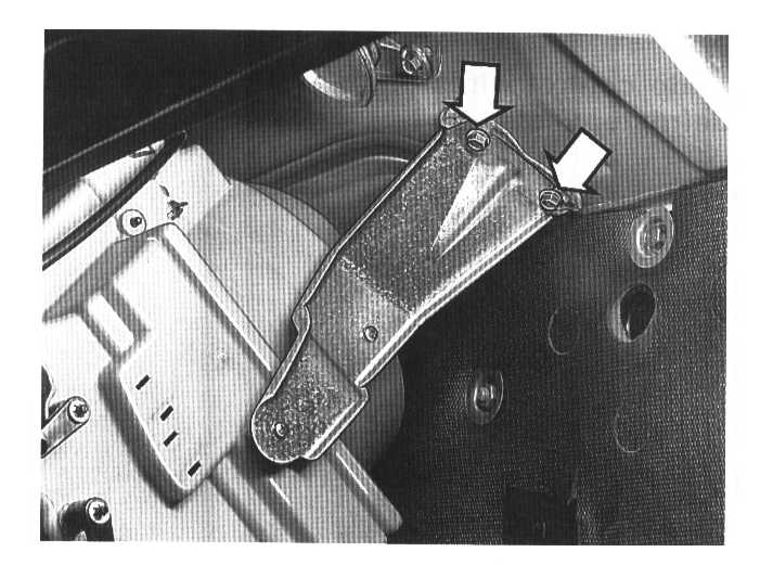
Install:
- heater from LH side.
- both upper mounting screws in firewall.
C25
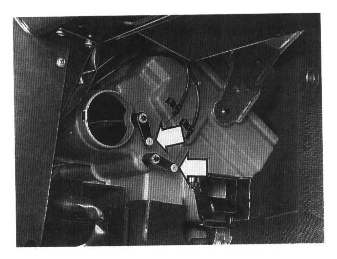
Connect wires and sheath to floor and defroster vents. Adjust vents
C26
Feed cell system drain hose into tunnel.
C27
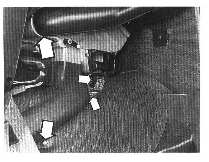
Install:
- lower heater mounting.
- air duct to rear floor.
- defroster hose.
C28
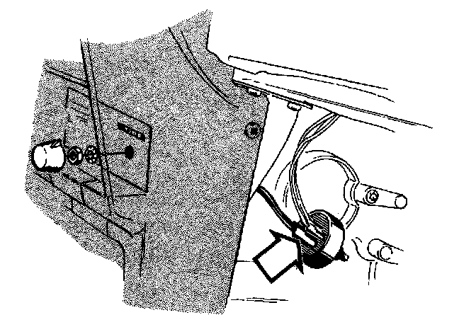
Connect heater positive lead to switch. Install switch in panel.
C29
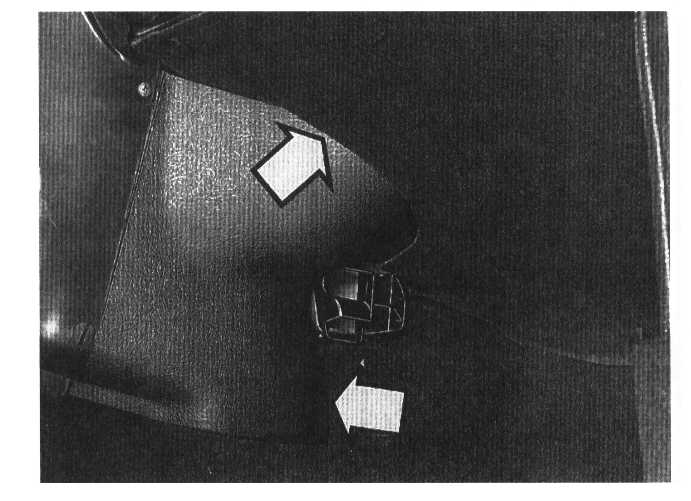
Turn floor mat back. Install sound insulation and side panel.
C30
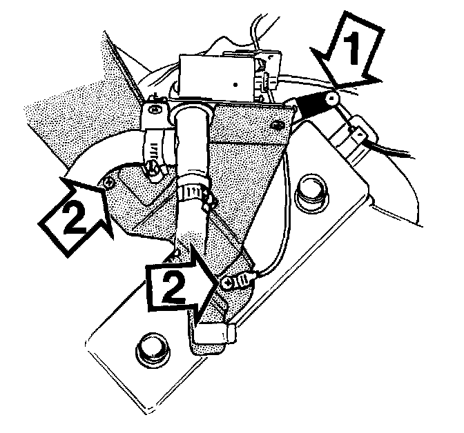
Install:
- control wire and sheath for air-mix (1). Adjust control.
- both upper mounting screws in heater housing (2) together with fan motor ground lead.
Note: Illustration shows versions B/C where the control valve remains in its bracket throughout.
Note: New heat control valve version and 1992 models onwards: Connect hoses to heater matrix. Tighten hose clips. Now remove hose pliers. Attach control wire to heat control valve.
Now go to C35.
VERSION A
C31
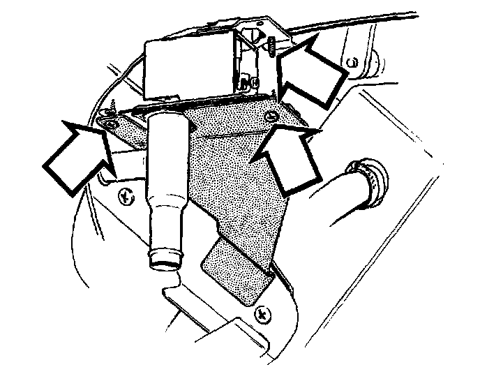
Connect control wire and sheath to control valve. Adjust control. Install control valve in bracket.
C32
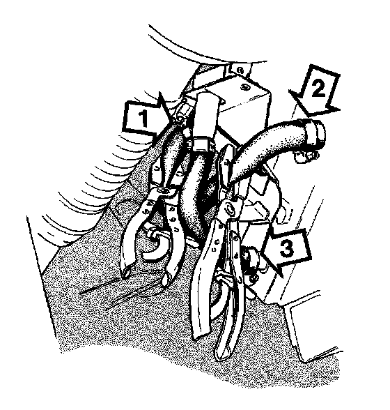
Connect hoses 1, 2 and 3. Remove hose pliers.
Go to step C35. Then go to step C40.
VERSIONS B AND C (B converted to C)
C33
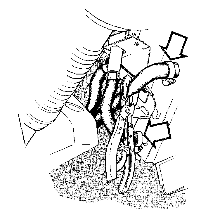
Connect hoses to cell system. Remove hose pliers
C34
Connect and adjust control wire.
C35
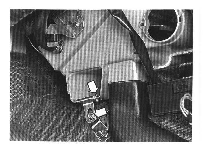
Install:
- both lower heater mounting screws.
- mounting screw to air duct to rear floor.
Note: New type heat control valve on 1992 models onwards: go to C40 - C44.
C36
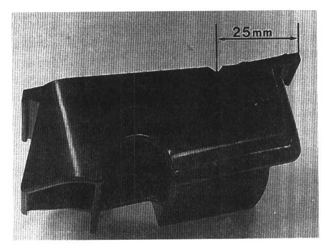
Make a 3 mm (0.118") cutout in the floor vent for the sensor head, 25 mm (0.984") from the RH edge:
The sensor head must fit tight.
C37
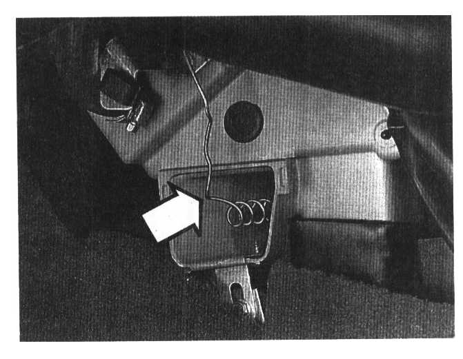
Straighten sensor head out slightly. Put coil in heater duct.
C38
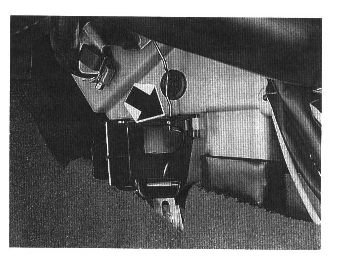
Install floor vent with sensor head in cutout:
Check that sensor head is not touching heater housing, otherwise there is a risk this may create unwanted noise. Fix sensor head in place with a piece of butyl tape it necessary.
C39
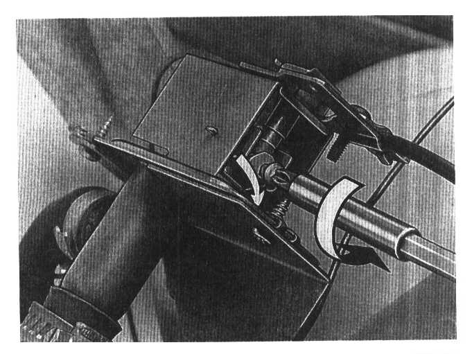
Adjust control valve:
Turn control valve adjustment screw 1/2 turn anticlockwise.
Note: Only make adjustment on control valve P/NG 1 3O7374-1. The number is embossed on the top of the valve mounting.
C40
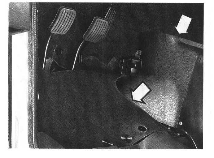
Install defroster hose. Turn floor mat back. Install sound insulation and side panel.
C41
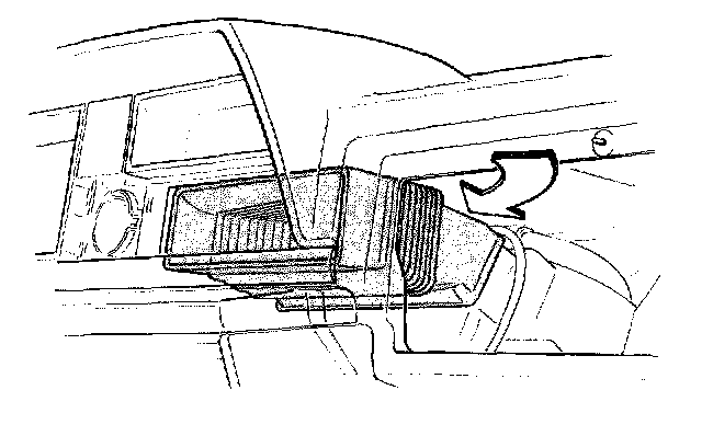
Install air duct between heater and vents.
C42
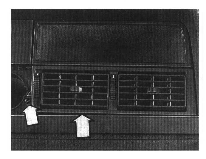
Install:
- vents.
- frame around vents.
- extra instrument cover.
C43
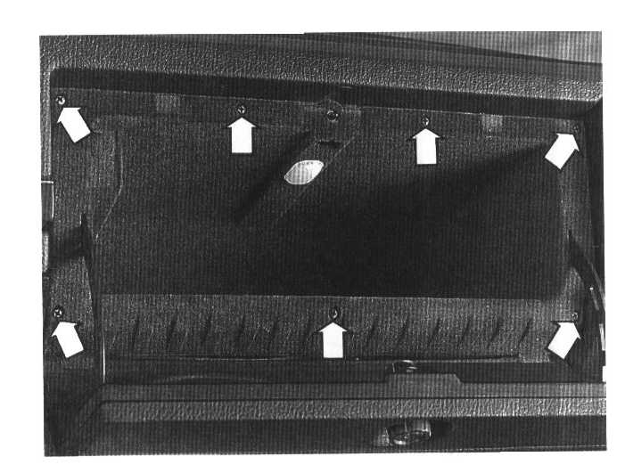
Install:
- glove compartment.
- battery negative lead.
C44
Check coolant level, top up if necessary.