Rear Subframe: Service and Repair
Subframe and Stone Impact Protection Overview
• Welding and straightening work on supporting or wheel carrying components of the suspension is not permitted.
• Always replace self-locking nuts.
• Always replace corroded bolts/nuts.
• Bonded rubber bushings can only be turned to a limited extent. Therefore, the threaded connections of the components with bonded rubber bushings should only be tightened when the wheel bearing housing is lifted (curb weight position). Refer to => [ Rear Axle, Lifting to Curb Weight Position ] Rear Axle, Lifting to Curb Weight Position.
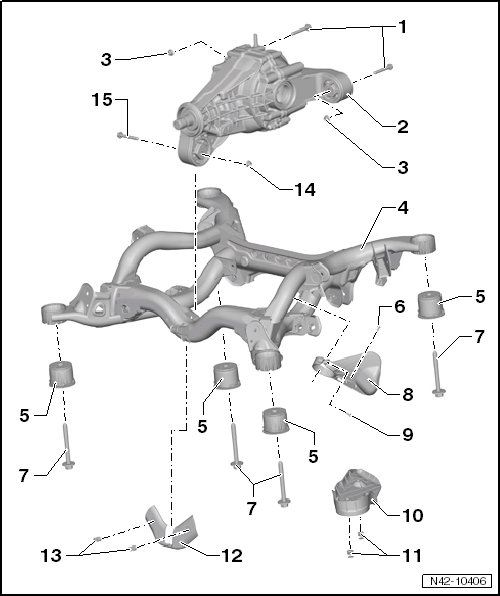
1 Bolt
• 90 Nm + 90° turn
• Quantity: 2
• Always replace if removed.
2 Rear Final Drive
3 Nut
• Quantity: 2
• Always replace if removed.
4 Subframe
• Locating, refer to => [ Subframe, Securing ] Description and Operation.
• Removing and Installing, refer to => [ Subframe ] Service and Repair.
• Replacing, bonded rubber mount in the forward direction of travel, refer to => [ Subframe Bonded Rubber Bushing, in the Forward Direction of Travel ] Subframe Bonded Rubber Bushing, in the Forward Direction of Travel.
• Replacing, bonded rubber mount in the backward direction of travel, refer to => [ Subframe Bonded Rubber Bushing, in the Backward Direction of Travel ] Subframe Bonded Rubber Bushing, in the Backward Direction of Travel.
5 Bonded Rubber Mount
• Removal and installation in the forward direction of travel, refer to => [ Subframe Bonded Rubber Bushing, in the Forward Direction of Travel ] Subframe Bonded Rubber Bushing, in the Forward Direction of Travel.
• Removal and installation in the backward direction of travel, refer to => [ Subframe Bonded Rubber Bushing, in the Backward Direction of Travel ] Subframe Bonded Rubber Bushing, in the Backward Direction of Travel.
6 Bolt
• 1 Nm
• For the correct allocation, refer to the Electronic Parts Catalog (ETKA).
7 Bolt
• 120 Nm + 180° turn
• Always replace if removed.
• For the correct allocation, refer to the Electronic Parts Catalog (ETKA).
8 Stone Protection Plate
• For the correct allocation, refer to the Electronic Parts Catalog (ETKA).
9 Bolt
• For the correct allocation, refer to the Electronic Parts Catalog (ETKA).
10 Stone Protection Plate
• For the correct allocation, refer to the Electronic Parts Catalog (ETKA).
11 Expanding Rivet
• For the correct allocation, refer to the Electronic Parts Catalog (ETKA).
12 Stone Protection Plate
• For the correct allocation, refer to the Electronic Parts Catalog (ETKA).
13 Expanding Rivet
• For the correct allocation, refer to the Electronic Parts Catalog (ETKA).
14 Nut
• 90 Nm + 90° turn
• Always replace if removed.
15 Bolt
• Always replace if removed.