Fuel Pump, Checking
Fuel Pump, Checking
=> [ Function and Voltage Supply, Checking ]
=> [ Delivery Quantity, Checking ]
=> [ Current Draw, Checking ]
=> [ Fuel Pump Check Valve, Checking ]
Special tools, testers and auxiliary items required
• Pressure Tester (VAS 6550)
• Remote Control (V.A.G 1348/3A)
• Test Instrument Adapter/DSO (5-pin) (VAS 5565)
• Multi-Meter (V.A.G 1715)
• Wrench (T10202)
• Torque Wrench (40-200 Nm) (V.A.G 1332)
• Voltage Tester (V.A.G 1527B)
• Vehicle Diagnostic Tester
• Measuring Container, 3 liter
Function and Voltage Supply, Checking
• Battery voltage at least 11.5 volts
• The fuse for the fuel pump is OK.
• The output diagnostic test mode checks the fuel pump.
- Connect the vehicle diagnostic tester as follows:
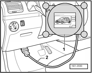
- Connect the diagnostic cable - 2 - to the Data Link Connection (DLC) inside the drivers footwell.
- Turn on the ignition.
- Press the buttons for "Vehicle Self-Diagnosis", "01 - Engine electronics" and "Output Diagnostic Test Mode (DTM)" on the display in succession.
- Press the right arrow button on the display to initiate the fuel pump activation.
The fuel pump must run.
• The fuel pump runs quietly.
- Turn off the ignition.
If the Fuel Pump Does Not Run:
- Remove the rear bench seat.
- Remove the cover - 1 - from the fuel delivery unit. The arrow - 2 - points in the direction of travel.
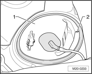
- First, pull on the connector - arrow - without pressing the retainer to make sure it connected securely. If the connector was not connected correctly, check the fuel pump function again.
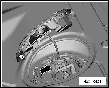
- Disconnect the connector.
- Check the contacts on the connector and the fuel delivery unit for damage.
- Install the test instrument adapter/DSO (5-pin) (VAS 5565) between the connectors on the fuel delivery unit and cover.
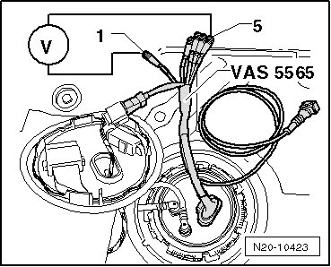
- Connect the voltage tester (V.A.G 1527 B) to the wires - 1 and 5 - on the test instrument adapter/DSO (5-pin) (VAS 5565).
- Turn the ignition on.
• The Light Emitting Diode (LED) must light up briefly.
If the LED does not light up briefly:
- Locate and repair the open circuit in the wiring using the wiring diagram.
If the LED lights up briefly (the voltage supply is OK):
- Replace the fuel delivery unit. Refer to => [ Fuel Delivery Unit ] Service and Repair.
- Check if the electrical wiring between the flange and fuel pump are connected.
If no open circuits are found:
- The fuel pump is faulty, replace the fuel delivery unit. Refer to => [ Fuel Delivery Unit ] Service and Repair.
Delivery Quantity, Checking
• Voltage supply is OK.
• The fuel pressure regulator and residual pressure is OK. Refer to => [ Fuel Pressure Regulator and Residual Pressure, Checking ] Testing and Inspection.
• The fuel filter is OK.
- Remove the fuel cap from the fuel filler tube.
- Remove the rear bench seat.
- Remove the cover - 1 - from fuel delivery unit. The arrow - 2 - points in the direction of travel.
- First, pull on the connector - arrow - without pressing the retainer to make sure it connected securely. If the connector was not connected correctly, it could cause a fault.
- Disconnect the connector.
- Check the contacts on the connector and the fuel delivery unit for damage.
- Install the test instrument adapter/DSO (5-pin) (VAS 5565) between the connectors on the fuel delivery unit and cover.
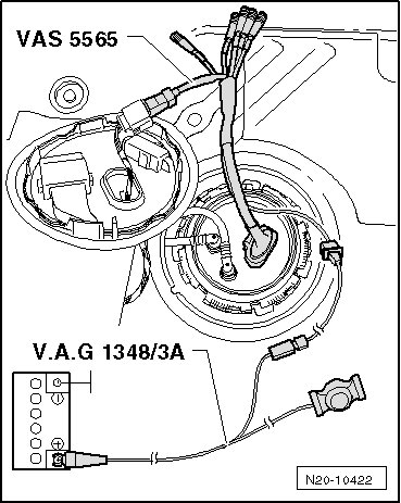
- Connect the remote control (V.A.G 1348/3A) to the test instrument adapter/DSO (5-pin) (VAS 5565) and to battery positive (+).
• This step allows the fuel pump to run when the engine is not running.
• The delivery rate of the fuel pump is measured at 4 bar. Therefore, measure the fuel pressure before measuring the delivery rate. Refer to => [ Fuel Pressure Regulator and Residual Pressure, Checking ] Testing and Inspection.
The fuel system is under pressure!
• Always wear protective eyewear and protective clothing to prevent injuries and fuel from coming in contact with your skin.
• Before loosening line connections, place a cloth around the connection point. Then release pressure by carefully pulling off the line.
- Disconnect the return line - 1 - from the fuel pressure regulator.
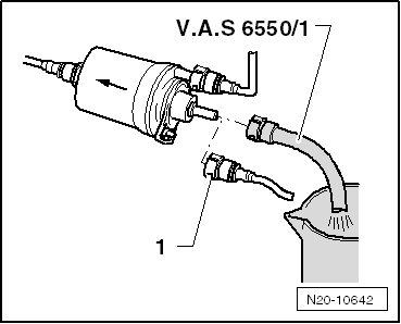
• Press in the securing ring to disengage the fuel line.
- Install the adapter (VAS 6550/1) to the fuel pressure regulator and hold the other end of the adapter in a measuring container.
- Operate the remote control (V.A.G 1348/3A) approximately 5 seconds in order to fill the fuel filter.
- Empty the measuring container.
- The fuel pump delivery rate depends on the voltage. So, connect the multi-meter (V.A.G 1715) to wires - 1 and 5 - on the test instrument adapter/DSO (5-pin) (VAS 5565).
- Operate the remote control for 60 seconds and simultaneously measure the voltage of the fuel pump.
- Compare the quantity of fuel delivered with the specification.
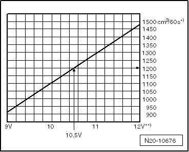
*) Minimum delivery rate cm3/60 s
**) Voltage of the fuel pump with engine running in idle and the pump is on.
Example:
During the test, a voltage of 10.5 volts is measured. This results in a minimum delivery quantity of approximately 1200 cm3/60 s.
If the minimum delivery rate is not attained:
- Check the fuel filter as follows:
The fuel system is under pressure!
• Always wear protective eyewear and protective clothing to prevent injuries and fuel from coming in contact with your skin.
• Before loosening line connections, place a cloth around the connection point. Then release pressure by carefully pulling off the line.
- Disconnect the fuel supply line - arrow - from the fuel filter.
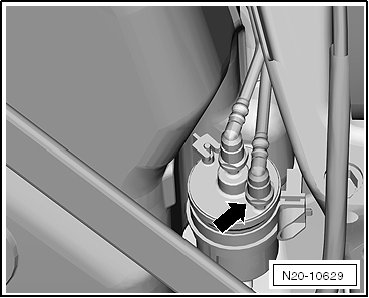
- Connect the pressure tester (VAS 6550) to the fuel supply line using the adapter (VAS 6550/1). Hold the other end of adapter (VAS 6550/2) in the measuring container.
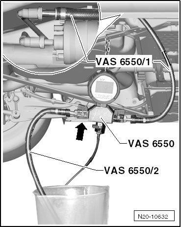
- Make sure the drain is closed and the shut off levers are open.
- Operate the remote control (V.A.G 1348/3A). Slowly close the shut off lever - A - until the pressure gauge reads 4 bar. From this point on do not move the position of the shut off lever.
- Empty the measuring container.
- Repeat the fuel delivery test.
If the minimum delivery rate is now obtained:
- Replace the fuel filter.
If the minimum delivery rate is again not obtained:
- Remove the fuel delivery unit and check the fuel strainer for contamination.
Only when up to now no malfunction has been detected:
- Replace the fuel delivery unit. Refer to => [ Fuel Delivery Unit ] Service and Repair.
- Reconnect all disconnected fuel lines.
- Bleed the fuel supply system. Refer to => [ Fuel System, Bleeding ] Service and Repair.
Delivery rate has been obtained, but malfunctions are still suspected in the fuel supply, for example sporadic loss of fuel supply:
- Check the fuel pump current draw. Refer to => [ Current Draw, Checking ].
Current Draw, Checking
- Remove the rear bench seat.
- Remove the cover - 1 - from the fuel delivery unit. The arrow - 2 - points in the direction of travel.
- First, pull on the connector - arrow - without pressing the retainer to make sure it connected securely. If the connector was not connected correctly, it could cause a fault.
- Disconnect the connector.
- Check the contacts on the connector and the fuel delivery unit for damage.
- Install the test instrument adapter/DSO (5-pin) (VAS 5565) between the connectors on the fuel delivery unit and cover.
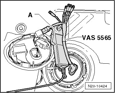
- Connect the current clamp - A - to the red wire of the test instrument adapter/DSO (5-pin) (VAS 5565) with the word "current clamp" on it.
- Start the engine and run at idle speed.
- Measure the current draw of the fuel pump.
Specified value: Max. 9 amps.
• If the malfunction in the fuel system is sporadic, the test can also be performed during a road test, but a second person is required.
If the current draw is exceeded:
- The fuel pump is faulty, replace the fuel delivery unit. Refer to => [ Fuel Delivery Unit ] Service and Repair.
Fuel Pump Check Valve, Checking
- Remove the rear bench seat.
- Remove the cover - 1 - from the fuel delivery unit. The arrow - 2 - points in the direction of travel.
- First, pull on the connector - arrow - without pressing the retainer to make sure it connected securely. If the connector was not connected correctly, it could cause a fault.
- Disconnect the connector.
- Check the contacts on the connector and the fuel delivery unit for damage.
- Install the test instrument adapter/DSO (5-pin) (VAS 5565) between the connectors on the fuel delivery unit and cover.
- Connect the remote control (V.A.G 1348/3A) to the test instrument adapter/DSO (5-pin) (VAS 5565) and to battery positive (+).
The fuel system is under pressure!
• Always wear protective eyewear and protective clothing to prevent injuries and fuel from coming in contact with your skin.
• Before loosening line connections, place a cloth around the connection point. Then release pressure by carefully pulling off the line.
- Disconnect the fuel supply line - arrow - from the fuel filter.
- Connect the pressure tester (VAS 6550) to the fuel supply line using the adapter (VAS 6550/1). Hold the other end of adapter (VAS 6550/2) in the measuring container.
- Close the shut off lever - A - on the pressure tester (VAS 6550) so the lever is perpendicular to the direction of flow.
- Operate the remote control in short intervals, until a pressure of approximately 4 bar has built up.
Danger of spraying when opening the shut off lever; wear protective goggles and protective clothing to prevent injuries and contact with skin. Hold the container in front of the free connection of the pressure measuring device.
- If pressure builds up too high, lower the excess pressure by carefully opening the shut off lever.
- Watch the pressure decrease on the pressure tester.
• After 10 minutes the pressure must not drop below a 3 bar decrease.
If the pressure drops further:
- Check the line connections for leaks.
If no fault is detected in the wiring:
- The fuel pump is faulty, replace the fuel delivery unit. Refer to => [ Fuel Delivery Unit ] Service and Repair.