Oil Filter: Service and Repair
Oil Filter Bracket with Attachments Overview
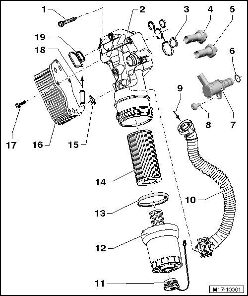
1 Bolt
• 25 Nm
2 Oil Filter Bracket
• Removing:
- Drain the coolant. Refer to => [ Draining and Filling ] Procedures.
- Remove the intake manifold. Refer to => [ Intake Manifold ] Intake Manifold.
- Disconnect the connection for the thermostat.
- Remove the coolant hose from the thermostat housing.
- Drain the oil filter housing, refer to => [ Oil Filter Housing, Draining ] Service and Repair and remove.
- Loosen the intake manifold support bolts.
- Remove the oil filter bracket, vent tube => [ (Item 10) Vent Tube ] remains connected.
3 Gasket
• Always replace
4 Reduced Oil Pressure Switch (F378)
• 20 Nm
• Blue, 1-pin connector.
• Installed location, refer to => [ Oil Pressure Switch and Oil Pressure Regulation Valve, Installed Position ].
• Checking, refer to "Guided Fault Finding" in the vehicle diagnostic tester.
5 Oil Pressure Switch (F1)
• 20 Nm
• Brown, 1-pin connector.
• Installed location, refer to => [ Oil Pressure Switch and Oil Pressure Regulation Valve, Installed Position ].
• Checking, refer to "Guided Fault Finding" in the vehicle diagnostic tester.
6 O-ring
• Always replace.
7 Oil Pressure Regulation Valve (N428)
• Installed location, refer to => [ Oil Pressure Switch and Oil Pressure Regulation Valve, Installed Position ].
• Checking, refer to "Guided Fault Finding" in the vehicle diagnostic tester.
8 Bolt
• 9 Nm
9 from the Connecting Pipe
• See => [ (Item 3) Connection ] Air Filter Housing Overview.
10 Vent Tube
• Due to the 4 point lock, only disconnect when oil filter bracket is to be removed.
11 Cap
12 Oil Filter Housing
• 25 Nm
• Remove and install using the oil filter wrench (3417).
• Draining, refer to => [ Oil Filter Housing, Draining ] Service and Repair.
13 Seal
• No replacement part, part of the oil filter.
• Install when lubricated.
• Installation position: Service flag upward.
14 Oil Filter Element
• Drain the oil filter housing before removing, refer to => [ Oil Filter Housing, Draining ] Service and Repair.
• Replacing, refer to Maintenance Procedures.
15 Gasket
• Always replace.
16 Oil Cooler
• See the note in => [ Oil Filter Bracket with Attachments Overview ] Service and Repair.
• Ensure sufficient clearance to surrounding components.
• Coolant hose connection diagram. Refer to => [ Coolant Hose Connection Diagram ] [1][2]Cooling System.
17 Bolt
• 25 Nm
18 to the Thermostat Housing
19 Gasket
• Always replace
Oil Pressure Switch and Oil Pressure Regulation Valve, Installed Position
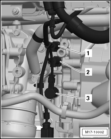
1 - Reduced oil pressure switch, blue
2 - Oil pressure switch, brown
3 - Oil pressure regulation valve