FS III Front Brake Overview
FS III Front Brake Overview
• After replacing brake pads, depress brake pedal several times firmly to properly seat brake pads in their normal operating position.
• Use Brake filling and bleeding equipment (VAS 5234) to extract brake fluid from brake fluid reservoir.
• Before removing a brake caliper or disconnecting a brake hose, the Brake pedal actuator (V.A.G1869/2) should be installed (relieve pressure).
Without Brake Pad Wear Display
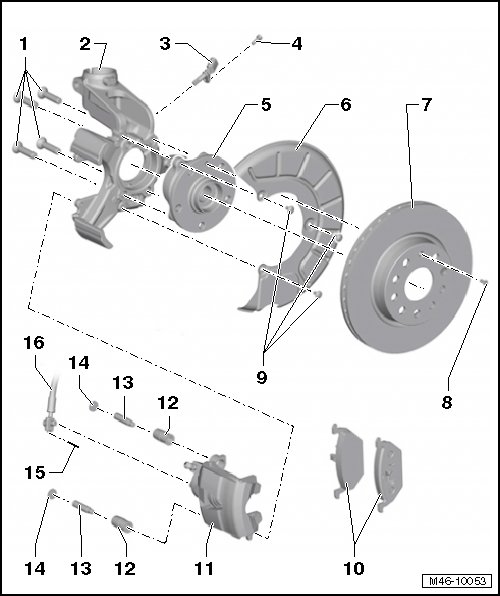
1 Bolt
• 70 Nm + 90°
• Always replace if removed.
• Quantity: 4
2 Wheel Bearing Housing
• With integrated brake carrier.
3 Front ABS Wheel Speed Sensor
• Clean the inside of the hole and coat it with hot bolt paste (G 052.112.A3) before installing the sensor.
4 Bolt
• 8 Nm
5 Wheel Bearing Unit
• The ABS sensor ring is installed in the wheel bearing.
6 Cover Plate
• Removing and installing, refer to => [ Cover Plate ] Cover Plate.
7 Brake Rotor
• Vented on the inside.
• Diameter 280 mm.
• Thickness 22 mm.
• Wear limit: 19 mm.
• Replace in pairs.
• Removing and installing, refer to => [ Brake Disc ] Brake Disc.
• Do not use excessive force to separate the brake rotor from the wheel hub. If necessary, use rust penetrant, otherwise the brake rotors could be damaged.
8 Bolt
• 5 Nm
9 Bolt
• 12 Nm
10 Brake Pads
• Thickness 14 mm without backing plate.
• Wear limit: 2 mm without backing plate.
• Checking thickness. Refer to Maintenance Procedures.
• Replace in pairs.
• Removing and installing, refer to => [ Brake Pads ] Brake Pads.
11 Brake Caliper
• Do not unscrew brake hose when replacing brake pad.
• Removing and installing, refer to => [ Brake Caliper ] Brake Caliper.
• Servicing, refer to=> [ FS III Front Brake Caliper Overview ] FS III Front Brake Caliper Overview.
12 Bushing
13 Guide Pins
• 30 Nm
14 Cap
• Remove
15 Adapter Sleeve
16 Brake Hose With Ring Connection and Banjo Fitting
• 35 Nm
• After replacing brake pads, depress brake pedal several times firmly to properly seat brake pads in their normal operating position.
• Use Brake filling and bleeding equipment (VAS 5234) to extract brake fluid from brake fluid reservoir.
• Before removing a brake caliper or disconnecting a brake hose, the Brake pedal actuator (V.A.G 1869/2) should be installed (relieve pressure).
With Brake Pad Wear Display
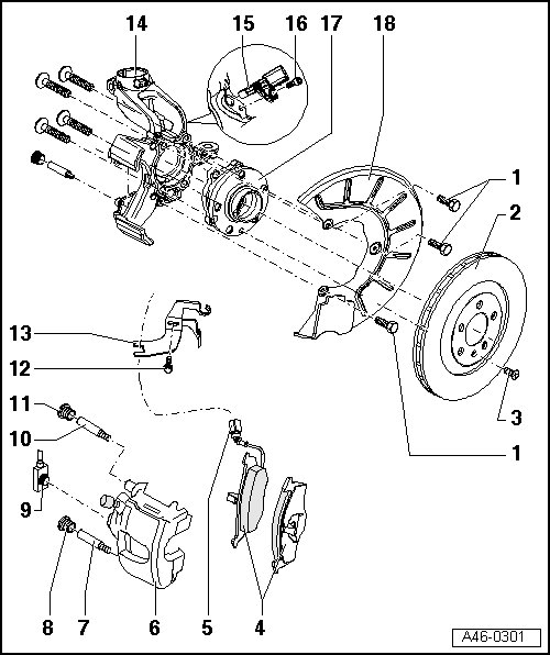
1 Bolt
• 12 Nm
• Quantity: 3
2 Brake Rotor
• Vented, 280 mm diameter.
• Thickness 22 mm.
• Wear limit: 19 mm.
• Must always be replaced together on both sides of axle.
• Remove brake caliper before removing.
3 Bolt
• 5 Nm
4 Brake Pads
• Thickness 14 mm without backing plate.
• With left front brake pad wear sensor (G34).
• When wear limit is reached (limit: approximately 4 mm) the brake system indicator lamp (K118) lights up in the instrument cluster.
• Wear limit: 2 mm with backing plate.
• Check brake pads, very thorough maintenance. Refer to Maintenance Procedures.
• Replace brake pads by axle.
• Removing and installing, refer to=> [ Brake Pads ] Brake Pads.
5 Harness Connector
• For left front brake pad wear sensor (G34).
6 Brake Caliper
• Do not unscrew brake hose when replacing brake pad.
• Removing and installing, refer to => [ Brake Caliper ] Brake Caliper.
• Servicing, refer to=> [ FS III Front Brake Caliper Overview ] FS III Front Brake Caliper Overview.
7 Guide Pins
• 30 Nm
8 Cap
• Remove
9 Brake Hose With Ring Connection and Banjo Fitting
• 35 Nm
10 Guide pins
• 30 Nm
11 Cap
• remove
12 Bolt
13 Bracket
14 Wheel Bearing Housing
• With integrated brake carrier.
15 Front ABS Wheel Speed Sensor
• Before inserting sensor, clean inner surface of bore hole and coat with hot bolt paste (G 052 112 A3).
16 Bolt
• 8 Nm
17 Wheel Bearing/Wheel Bearing Unit
• The ABS sensor ring is installed in the wheel bearing.
18 Cover Plate
• Removing and installing, refer to => [ Cover Plate ] Cover Plate.