Diesel Particle Filter (DPF): Service and Repair
Particulate Filter with NOx Reduction Catalytic Converter Overview
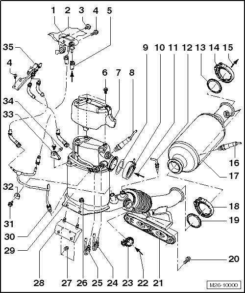
1 Exhaust Pressure Sensor 1 (G450)
• Bolted near the oil filler neck.
2 Heat Shielding
• Replace if damaged.
3 Bolt
• 8 Nm
4 Bolt
• 4 Nm
5 Control Line
• Make sure it is secure.
• From the Exhaust Gas Recirculation (EGR) housing.
6 Bolt
• 10 Nm
7 Heat Shield
• Pay attention to the installed position.
8 Heated Oxygen Sensor (G39)
• 52 Nm
• Use the ring spanner 7-piece set (3337) to loosen and tighten.
• Lubricate the threads using hot bolt paste (G 052 112 A3) only, do not let the paste get into the slots on the oxygen sensor body.
9 Seal
• Always replace.
10 Securing Clamp
• 7 Nm
• Always replace.
• Note the installed position. Refer to => [ Clamps and Exhaust Gas Temperature Sensor, Installed Position ] Service and Repair.
11 from the Turbocharger
12 Exhaust Gas Temperature Sensor 4 (G648)
• 45 Nm
• Mark the installed position before removing.
• Coat only the threads with hot bolt paste (G 052 112 A3).
• Wire routing, refer to => [ Exhaust System Component Wire Routing ] Description and Operation.
13 Seal
• Always replace.
• Installing, refer to => [ Installing the Seal between the Exhaust Door Control Unit and Exhaust Pipe with Catalyst and Particulate Filter or the NOx Reduction Catalytic Converter ] Exhaust Door Control Unit With NOx Reduction Catalytic Converter Overview.
14 Securing Clamp
• 7 Nm
• Always replace.
• Note the installed position, refer to => [ Installed Position of the Clamp between the Exhaust Door Control Unit and NOx Reduction Catalytic Converter or Exhaust Pipe with Catalyst and Particulate Filter ] Exhaust Door Control Unit With NOx Reduction Catalytic Converter Overview.
15 to the Exhaust Door Control Unit (J883)
16 Oxygen Sensor after Three Way Catalytic Converter (G130)
• 52 Nm
• Use the ring spanner 7-piece set (3337) to loosen and tighten.
• Lubricate the threads with hot bolt paste (G 052 112 A3) only, do not let the paste get into the slots on the oxygen sensor body.
• Wire routing, refer to => [ Exhaust System Component Wire Routing ] Description and Operation.
17 NOx Reduction Catalytic Converter
The coupling elements between the particulate filter and NOx reduction catalytic converter can be damaged. When removing and installing:
• Do not bend the coupling element more than 10°.
• Do not stretch the coupling element.
• Do not damage the wire mesh on the coupling element.
• Use the transportation lock (T10404) to secure the unlocking element from over-bending.
• Removing and Installing, refer to => [ Particulate Filter with NOx Absorption Catalytic Converter ] Service and Repair.
18 Securing Clamp
• 7 Nm
• Always replace.
• Note the installed position, refer to => [ Clamps and Exhaust Gas Temperature Sensor, Installed Position ] Service and Repair.
19 Seal
• Always replace.
20 Bolt
• 25 Nm
21 Suspended Mount
• Install without tension.
22 from the Exhaust Gas Recirculation (EGR) Filter
23 Securing Clamp
• 3.5 Nm
• Always replace.
• Note the installed position, refer to => [ Clamps and Exhaust Gas Temperature Sensor, Installed Position ] Service and Repair.
24 Exhaust Gas Temperature Sensor 2 (G448)
• 45 Nm
• Note the installed position, refer to => [ Clamps and Exhaust Gas Temperature Sensor, Installed Position ] Service and Repair.
• Coat only the threads with hot bolt paste (G 052 112 A3).
25 Exhaust Gas Temperature Sensor 3 (G495)
• 45 Nm
• Note the installed position, refer to => [ Clamps and Exhaust Gas Temperature Sensor, Installed Position ] Service and Repair.
• Coat only the threads with hot bolt paste (G 052 112 A3).
26 Nut
• 23 Nm
27 Nut
• 23 Nm
28 Bracket
• Pay attention to the installed position.
• For the particulate filter.
• Fastened to cylinder block.
• Install without tension.
29 Particulate Filter
The coupling elements between the particulate filter and NOx reduction catalytic converter can be damaged. When removing and installing:
• Do not bend the coupling element more than 10°.
• Do not stretch the coupling element.
• Do not damage the wire mesh on the coupling element.
• Use the transportation lock (T10404) to secure the unlocking element from over-bending.
• Removing and installing, refer to => [ Particulate Filter with NOx Absorption Catalytic Converter ] Service and Repair.
• After replacing, set the soot load measurement adaptation to "0". Refer to "Guided Functions" in the vehicle diagnostic tester.
30 Control Line
• 45 Nm
• Do not change the angles of the control line.
• Install without tension.
31 Bolt
• 9 Nm
32 Bracket
• For the control line.
• Install without tension.
33 Bracket
• Pay attention to the installed position.
• For the particulate filter.
• Fastened to the cylinder head.
• Install without tension.
34 Bolt/Nut
• 23 Nm
35 Differential Pressure Sensor (G505)
• Bolted onto the bracket for the auxiliary fuel pump/fuel pump 2.