Subframe with Hydraulic Steering Gear
Subframe with Hydraulic Steering Gear
Special tools, testers and auxiliary items required
• Hose Clamps up to 25 mm (3094)
• Ball Joint Puller (T10187)
• Torque Wrench 5-50 Nm (V.A.G 1331)
• Torque Wrench 40-200 Nm (V.A.G 1332)
• Engine/Gearbox Jack (V.A.G 1383 A)
• Shop Crane Drip Tray (VAS 6208)
Removing
- Turn the steering wheel to the straight-ahead position and remove the ignition key so that the steering wheel lock engages.
Vehicle with "Keyless Access" Keyless Locking and Starting System
- Switch the ignition off and open the driver's door so the steering wheel lock locks.
Continuation for All Vehicles
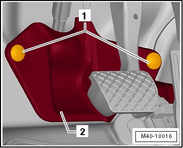
- Remove the bolts - 1 - and remove the footwell trim panel - 2 -.
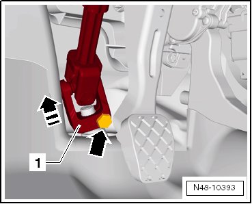
- Remove the bolt - arrow - from the universal joint - 1 -. Then remove the universal joint in - direction of arrow -.
- Clamp off suction and return hose on the power steering fluid reservoir.
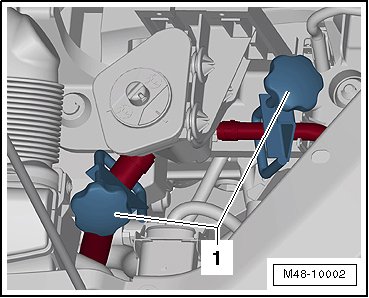
1. (3094)
- Loosen the wheel bolts.
- Raise the vehicle.
- Remove the front wheels.
- Remove the lower noise insulation.
- Remove exhaust system bracket from subframe - arrows -.
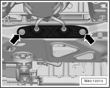
- Loosen the double clamp for the exhaust system.
- Remove the left and right nut - 1 - from the coupling rod - 3 -.
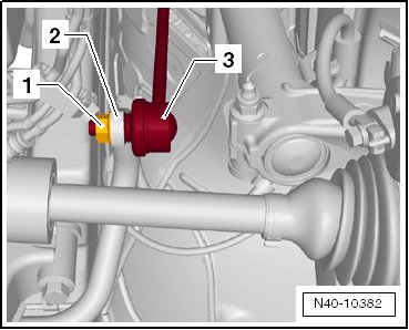
- Remove the coupling rod - 3 - from the stabilizer bar - 2 - on the left and right sides.
- Remove the nuts - arrows - on left and right side of vehicle.
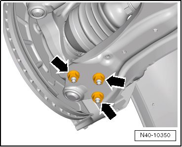
- Remove the control arm from the ball joint.
- Loosen nut of track rod ball joint, but do not unscrew yet.
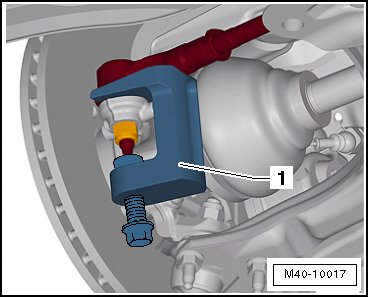
To protect thread, screw nut on pin a few turns.
- Remove the tie rod end from the wheel bearing housing and remove the nut.
1. (T10187)
- Remove pendulum support from transmission, unscrew bolts - 11 - to do so.
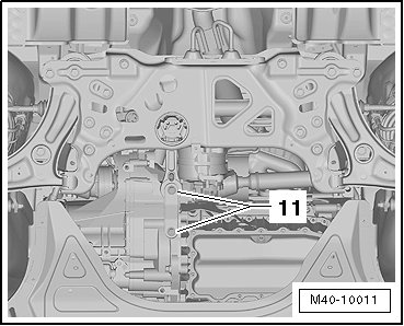
- Remove the wire for the service interval extension from the subframe.
- Subframe, locating, refer to => [ Subframe, Securing ] Subframe, Securing.
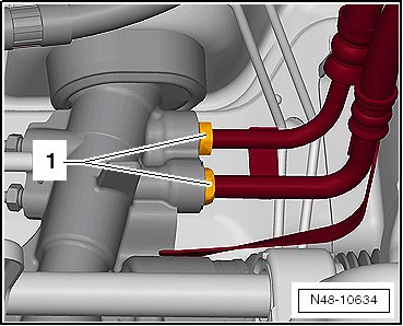
- Remove the pressure line and return line - 1 - from the steering gear.
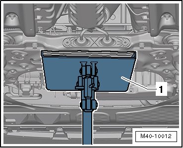
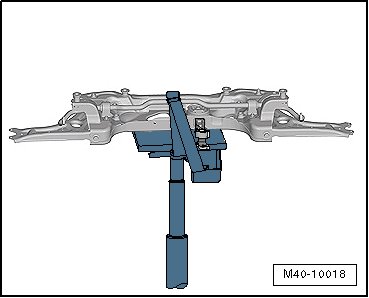
- Move the (V.A.G 1383 A) - 1 - under the subframe.
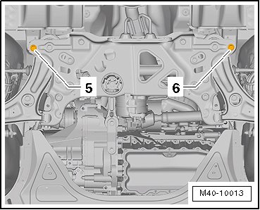
- Remove the bolts - 5 - and - 6 - and lower the subframe with the (V.A.G 1383 A).
- Secure the subframe to the (V.A.G 1383 A) with the accompanying strap.
Installing
Install in reverse order of removal. Note the following:
• Pay attention to the installed position of the hydraulic lines on the steering gear.
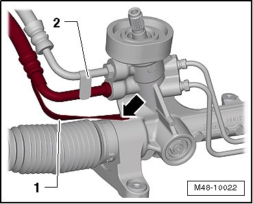
• The strap - 1 - on the hose must be supported by the steering gear - arrow -.
• The strap - 2 - on the return hose must be supported by the hose.
- Always make sure the intermediate plate - 1 - is installed between the subframe - 2 - and the body.
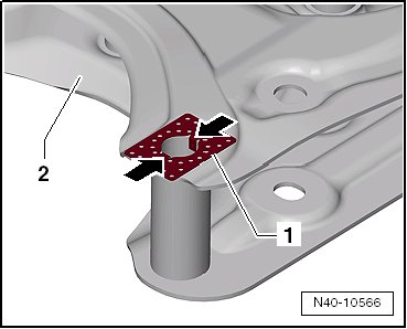
Insert the long side of the intermediate plate - 1 - so that it is perpendicular to direction of travel. The tabs - arrows - fit into the subframe - 2 -.
- Install the noise insulation.
- Install front wheels and tighten. Refer to => [ Wheel Bolt Tightening Specification ] Specifications.
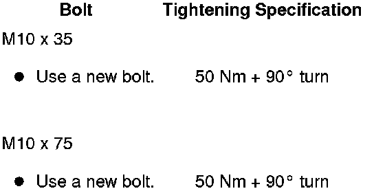
Tightening Specifications
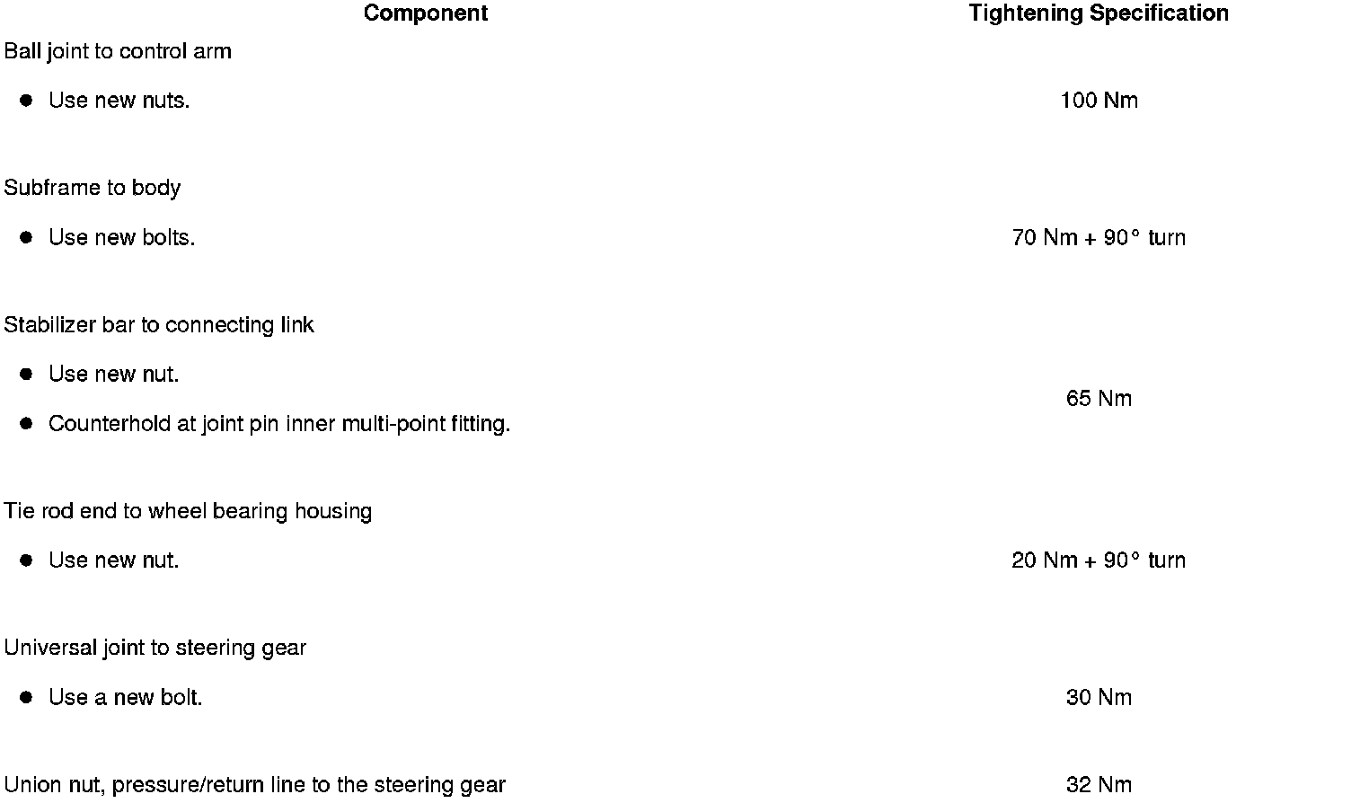
Tightening Specification, Pendulum Support to the Transmission