EVAP System Overview
EVAP System Overview
=> [ Vehicles through MY 2009 ]
=> [ Vehicles from MY 2010 ]
Vehicles through MY 2009
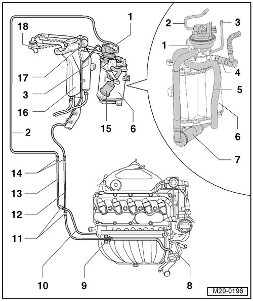
1 Leak Detection Pump (LDP) (V144)
• Component location: Under the wheel housing liner in the right rear wheel housing.
• On the Evaporative Emission (EVAP) canister.
• Checking, refer to Vehicle diagnosis, testing and information system VAS 5051B.
• Removal and installation, refer to => [ EVAP Canister and Leak Detection Pump ] Service and Repair.
2 Vacuum Line
• From the LDP to the intake manifold.
• Component location: Under the wheel housing liner in the right rear wheel housing.
3 Vent Line
• To the EVAP canister purge regulator valve (N80 )
4 Vent Line
• Engine code BPS: from the switch over valve - item 7 - in => [ Switch Over Valve ] at fuel tank.
• Engine code BPR: From the fuel tank, see - item 10 - in => [ to EVAP Canister ] Removal and Replacement.
• To disengage, push the securing ring forward.
5 Connecting Line
• From the LDP to the EVAP canister.
6 Evaporative Emission (EVAP) Canister
• Component location: Under the wheel housing liner in the right rear wheel housing.
• Assembly overview, refer to => [ EVAP System Assembly Overview ] EVAP System Assembly Overview.
• Removal and installation, refer to => [ EVAP Canister and Leak Detection Pump ] Service and Repair.
7 Auxiliary Filter
• Attached to the EVAP canister.
• See - item 5 - in => [ Auxiliary Filter ] EVAP System Assembly Overview.
8 Throttle Valve Control Module (J338)
Removal and installation, refer to => [ Throttle Valve Control Module ] Service and Repair.
9 Evaporative Emission (EVAP) Canister Purge Regulator Valve 1 (N80)
• Checking, refer to Vehicle diagnosis, testing and information system VAS 5051B.
10 Vacuum Line
• connected to the intake manifold.
11 Separating Point
• In the right front of the engine compartment under the coolant expansion tank
12 Vent Line
• White
• From the EVAP canister to the EVAP canister purge regulator valve.
• Installed position: on the right side of the underbody.
• Secured to the fuel tank.
13 Vacuum Line
• Green
• From the engine to the LDP.
• Installed position: on the right of the underbody.
• Secured to the fuel tank.
14 Separating Point
• In the right front on the fuel tank in the area of the fuel filter.
15 Air Filter Housing
• For the LDP.
16 Fuel Filler Tube
17 Pressure Retention Valve
• Only with engine code BPS.
• For fuel tank ventilation.
18 Gravity Valve
• Only with engine code BPS.
• To remove the valve, unclip upward out of the support.
Vehicles from MY 2010
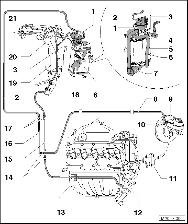
1 Leak Detection Pump (LDP) (V144)
• Component location: Under the wheel housing liner in the right rear wheel housing.
• On the Evaporative Emission (EVAP) canister.
• Checking, refer to Vehicle diagnosis, testing and information system VAS 5051B.
• Removal and installation, refer to => [ EVAP Canister and Leak Detection Pump ] Service and Repair.
2 Vacuum Line
• From the LDP to the intake manifold.
• Component location: Under the wheel housing liner in the right rear wheel housing.
3 Vent Line
• To the EVAP canister purge regulator valve.
4 Vent Line
• Engine code BPS: from the switch over valve - item 7 - in => [ Switch Over Valve ] at fuel tank.
• Engine code BPR: from fuel tank see - item 10 - in => [ to EVAP Canister ] Removal and Replacement.
• To disengage, push securing ring forward.
5 Connecting Line
• From the LDP to the EVAP canister.
6 Evaporative Emission (EVAP) Canister
• Component location: Under the wheel housing liner in the right rear wheel housing.
• Assembly overview, refer to => [ EVAP System Assembly Overview ] EVAP System Assembly Overview.
• Removal and installation, refer to => [ EVAP Canister and Leak Detection Pump ] Service and Repair.
7 Auxiliary Filter
• Attached to the EVAP canister.
• See - item 5 - in => [ Auxiliary Filter ] EVAP System Assembly Overview.
8 Vacuum Line
• Connection to the vacuum line between the vacuum pump and the brake booster - item 10 -.
• Attached to the bulkhead with 2 clips.
9 Brake Booster
10 Vacuum Line, from the Vacuum Pump to the Brake Booster
11 Vacuum Pump
12 Throttle Valve Control Module (J338)
Removal and installation, refer to => [ Throttle Valve Control Module ] Service and Repair.
13 Evaporative Emission (EVAP) Canister Purge Regulator Valve 1 (N80)
• Checking, refer to Vehicle diagnosis, testing and information system VAS 5051B
14 Separating Point
• At the right front in the engine compartment under the coolant expansion tank.
15 Vent Line
• White
• From the EVAP canister to the EVAP canister purge regulator valve.
• Installed position: on the right side of the underbody.
• Secured to the fuel tank.
16 Vacuum Line
• Green
• From the engine to the LDP.
• Installed position: on the right side of the underbody.
• Secured to the fuel tank.
17 Separating Point
• On the right front on the fuel tank in the area of the fuel filter.
18 Air Filter Housing
• For the LDP.
19 Fuel Filler Tube
20 Pressure Retention Valve
• Only with engine code BPS.
• For fuel tank ventilation.
21 Gravity Valve
• Only with engine code BPS.
• To remove the valve, unclip upward out of the support.