Oil Filter: Service and Repair
Oil Filter, Oil Cooler and Oil Pressure Switch Overview
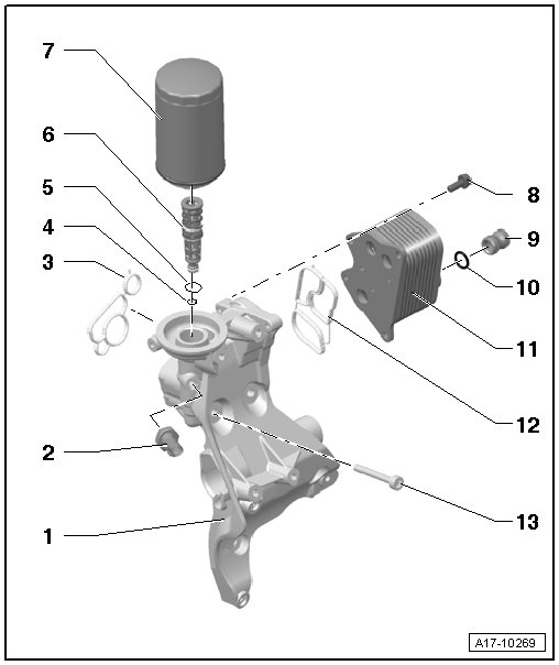
1 Accessory Bracket
• Removing and installing, refer to => [ Accessory Bracket ] Service and Repair.
2 Oil Pressure Switch (F1)
• 20 Nm
• 1.4 bar - black
• Checking, refer to => [ Oil Pressure and Switch, Checking ] Testing and Inspection.
• Remove using the socket 24 mm and jointed extension (T40175).
3 Gasket
• Always replace.
4 O-ring
• No replacement part, part of the valve unit.
5 O-ring
• No replacement part, part of the valve unit.
6 Valve Unit
• With the O-rings.
7 Oil Filter Element
• 22 Nm
• See the notes in => [ If metal shavings or a large quantity
of small metal particles are found when repairing an engine, this
could indicate that the crankshaft or connecting rod bearings are
damaged. To prevent further damage, perform the following steps after
the repair: ] Oil Pan and Oil Pump.
• Remove and install using the oil filter wrench (3417).
8 Bolt
• 15 Nm
9 Connection
10 Seal
• Always replace
11 Oil Cooler
• See the notes in => [ If metal shavings or a large quantity
of small metal particles are found when repairing an engine, this
could indicate that the crankshaft or connecting rod bearings are
damaged. To prevent further damage, perform the following steps after
the repair: ] Oil Pan and Oil Pump.
• Ensure sufficient clearance to surrounding components.
• Removing and installing, refer to => [ Oil Cooler ] Oil Cooler.
• Coolant hose connection diagram. Refer to one of the following:
• With a manual transmission, refer to => [ Coolant Hose Connection Diagram ] [1][2]Cooling System
• With a Direct Shift Gearbox (DSG), refer to => [ Coolant Hose Connection Diagram ] [1][2]Cooling System
12 Gasket
• Always replace.
13 Bolt
• Tightening sequence and specification. Refer to => [ Accessory Bracket Bolt Tightening Sequence
and Specification ] Ribbed Belt Overview.