Variable Valve Timing Actuator: Service and Repair
Camshaft Adjuster Valves
Special tools, testers and auxiliary items required
• Torque wrench (5-60 Nm) (VAG 1783)
• TORX(R) bit set (VAG 1766)
• Ratchet insert 1/4" (VAS 6234)
• Socket wrench (T10072)
Removing
- Remove the intake manifold. Refer to => [ Intake Manifold ] Intake Manifold.
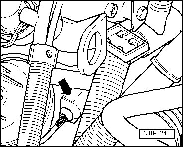
- Disconnect the 2 pin electrical connector - arrow - from the Engine Coolant Temperature (ECT) sensor.
- Drain the cooling system. Refer to => [ Draining and Filling ] Draining and Filling.
- Remove the coolant thermostat housing. Refer to => [ Coolant Thermostat Housing Assembly Overview ] Service and Repair.
- Remove the cylinder head cover. Refer to => [ Cylinder Head Cover ] Cylinder Head Cover.
- Disconnect the Secondary Air Injection (AIR) pressure hoses - item 18 - in the => [ Secondary Air Injection System Components Assembly Overview ] Secondary Air Injection System Components Assembly Overview.
• Before disconnecting the harness electrical connectors, mark the allocation to the component.
- Disconnect the electrical connectors from the Camshaft Position (CMP) sensor - 1 - and the CMP sensor 2 - 2 -.
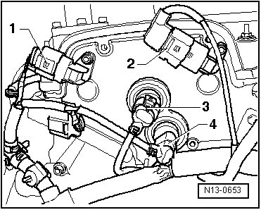
- Disconnect the electrical connectors - 3 and 4 -.
- Free up the wiring harness.
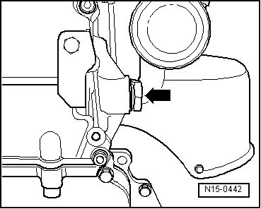
- Remove the camshaft roller chain tensioner - arrow -.
- Remove the timing chain cover bolts - arrows -.
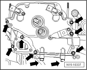
- When all the bolts have been removed, the cover can be carefully pried off.
CAUTION!
• Do not completely remove the camshaft adjustment valve bolts so that the valve is not tilted when removed.
• Carefully cover the lower chain compartment so no parts can fall in.
- Loosen the camshaft adjustment valve bolts approximately 3 mm (5 turns) - arrows - using (T10072).
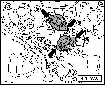
- Pull the camshaft adjustment valves out of the seal seat in the control housing against the loosened bolts.
- Completely remove the bolts and remove the camshaft adjustment valves from the control housing.
Installing
CAUTION!
• The valve seat in the control housing must not be scored or scratched.
• The camshaft adjustment valves and control housing must be free of dust and contamination.
• The camshaft adjustment valves must not be subjected to knocks or impacts.
• Only remove the new camshaft adjustment valve from the packaging right before installation.
• The camshaft adjustment valves must not be pulled into the valve seat by the bolts. Only press them in by hand.
- Lubricate the sealing rings with clean engine oil.
- Carefully insert the camshaft adjustment valve into the housing and press it perpendicular to the valve axle by hand until seated.
- Tighten the bolts - arrows - to 3.8 Nm.
- 1 - Camshaft adjustment valve 1.
- 2 - Camshaft adjustment valve 1 (exhaust).
- Clean the sealing surface on the timing chain cover as well as on the cylinder head.
- Lubricate the oil channel seal O-ring - item 13 - in the => [ Cylinder Head and Cover Assembly Overview ] Cylinder Head and Cover Assembly Overview, and insert it in the cover.
- Insert the seal - item 20 - in the => [ Cylinder Head and Cover Assembly Overview ] Cylinder Head and Cover Assembly Overview, into the timing chain cover.
- Clean the old sealing compound from the 3 mm holes in the cylinder head gasket - arrows -.
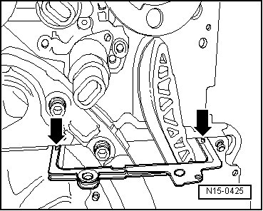
- Fill the 3 mm holes the in the cylinder head gasket with sealant (D 176 501) and install the sealant (D 176 501)on the sealing surfaces of the timing chain cover.
• With the cylinder head installed only half of the holes in the cylinder head gasket are visible.
- Install the timing chain cover as quickly as possible.
- Install the timing chain cover bolts - arrows - and tighten lightly.
- Tighten the M8 bolts - item 8 - in => [ Timing Chain Cover Assembly Overview ] Timing Chain Cover Assembly Overview to 23 Nm and tighten the M6 bolts - item 2 - in => [ Timing Chain Cover Assembly Overview ] Timing Chain Cover Assembly Overview to 8 Nm.
- Install the camshaft roller chain tensioner - item 15 - in the => [ Cylinder Head and Cover Assembly Overview ] Cylinder Head and Cover Assembly Overview and tighten it to 40 Nm.
- Install the cylinder head cover. Refer to => [ Cylinder Head Cover ] Cylinder Head Cover.
- Install the intake manifold. Refer to => [ Intake Manifold ] Intake Manifold.
The rest of the assembly is basically a reverse of the removal sequence.