Oxygen Sensor Heater Z29, Checking
Oxygen Sensor Heater Z29, Checking
• Oxygen Sensor (O2S) 1 (behind Three Way Catalytic Converter (TWC)) Heater (Z29) is part of Oxygen Sensor (O2S) Behind Three Way Catalytic Converter (TWC) (G130) and cannot be serviced separately.
• Vehicle must be raised before electrical harness connector for the Oxygen Sensor (O2S) Behind Three Way Catalytic Converter (TWC) (G130) is accessible.
• When servicing terminals in harness connector of Oxygen Sensor (O2S) Behind Three Way Catalytic Converter (TWC) (G130), use only gold-plated terminals.
Special tools, testers and auxiliary items required
• Multimeter.
• Wiring diagram.
Test requirements
• Fuse (SB12) OK.
• Battery voltage at least 12.5 volts.
• All electrical consumers such as, lights and rear window defroster, switched off.
• Vehicles with automatic transmission, shift selector lever into position " P" or "N".
• A/C switched off.
• Ground (GND) connections between engine/transmission/chassis OK.
• Ignition switched off.
Test procedure
- Perform a preliminary check to verify the customers complaint. Refer to => [ Preliminary Check ] Preliminary Check.
Start diagnosis
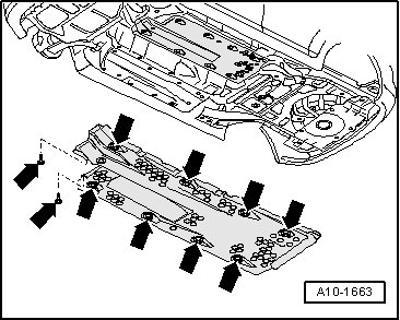
- Remove the right vehicle floor cover - arrows -.
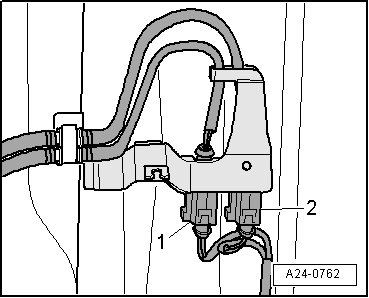
- Disconnect the Oxygen Sensor (O2S) Behind Three Way Catalytic Converter (TWC) (G130) electrical harness connector - 2 -.
Checking internal resistance
- Using a multimeter, check the Oxygen Sensor (O2S) Behind Three Way Catalytic Converter (TWC) (G130) terminals 1 to 2 for resistance.
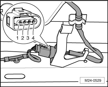
Specified value: 1.0 to 20.0 ohms (at approx. 20° C)
If the specification was not obtained:
- Replace Oxygen Sensor (O2S) Behind Three Way Catalytic Converter (TWC) (G130).
If the specification was obtained:
Checking voltage supply
- Using a multimeter, check the Oxygen Sensor (O2S) Behind Three Way Catalytic Converter (TWC) (G130) electrical harness connector terminal 1 to ground (GND) for voltage.
- Crank the engine.
Specified value: Battery voltage.
- Switch the engine off.
If the specification was not obtained:
- Check the Oxygen Sensor (O2S) Behind Three Way Catalytic Converter (TWC) (G130) electrical harness connector terminal 1 to the Motronic Engine Control Module (ECM) Power Supply Relay (J271) socket 2/87 for an open circuit, a short circuit to each other, Battery (+), or Ground (GND).
- Check the electrical harness connector for damage, corrosion, loose or broken terminals.
- If necessary, repair the faulty wiring connection.
If the specification was obtained:
Checking Ground (GND) activation
If the specified value was not obtained:
If the manufacturers test box is being used. Perform the following step.
- Install the test box.
If the manufacturers test box is not being used. Perform the following step.
- Remove the Engine Control Module (ECM) (J623). Refer to => [ Engine Control Module J623, Replacing ] Engine Control Module J623, Replacing.
- Using a multimeter, check the Oxygen Sensor (O2S) Behind Three Way Catalytic Converter (TWC) (G130) electrical harness connector to the Engine Control Module (ECM) (J623) electrical harness connector T121 for resistance.
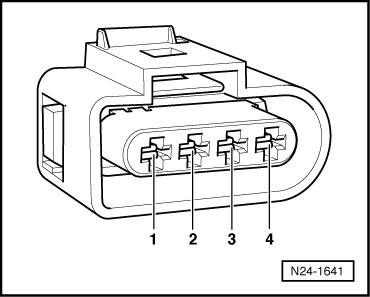

Specified value: 1.5 ohms max.
If the specification was not obtained:
- Check the wiring for an open circuit, a short circuit to each other, Battery (+), or Ground (GND).
- Check the electrical harness connector for damage, corrosion, loose or broken terminals.
- If necessary, repair the faulty wiring connection.
If no malfunction is found in the wiring and if the voltage supply was OK:
- Erase the DTC memory. Refer to => [ Diagnostic Mode 04 - Erase DTC Memory ] Diagnostic Mode 04 - Erase DTC Memory.
- Perform a road test to verify repair.
If the DTC does not return:
Repair complete, Generate readiness code. Refer to => [ Readiness Code Description ] Readiness Code Description.
- End diagnosis.
If the DTC returns and no malfunction is found in the wiring and the voltage supply was OK:
- Replace the Engine Control Module (ECM) (J623 ). Refer to => [ Engine Control Module J623, Replacing ] Engine Control Module J623, Replacing.
- Assembly is performed in the reverse of the removal.
Final procedures
After repair work, the following work steps must be performed in the following sequence:
1. Check the DTC memory. Refer to => [ Diagnostic Mode 03 - Read DTC Memory ] Diagnostic Mode 03 - Read DTC Memory.
2. If necessary, erase the DTC memory. Refer to => [ Diagnostic Mode 04 - Erase DTC Memory ] Diagnostic Mode 04 - Erase DTC Memory.
3. If the DTC memory was erased, generate readiness code. Refer to => [ Readiness Code ] Readiness Code.
End of diagnosis