Transverse Link, Tie Rod Assembly Overview
R32 Components, All Wheel Drive, Aluminum Subframe
Transverse Link, Tie Rod Assembly Overview
The - arrow - points in driving direction.
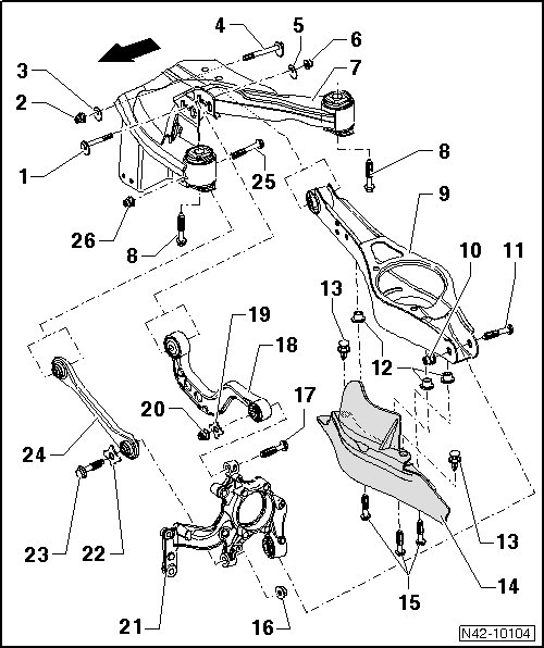
1 Eccentric Bolt
• After loosening, perform vehicle alignment, refer to => [ Vehicle Alignment Procedure Overview ] Vehicle Alignment Procedure Overview
• Do not turn more than 90° right or left (that is smallest to largest possible adjustment)
2 Nut
• Always replace after removal
• 95 Nm
• M12 x 1.5
• Self-locking
• Always tighten threaded connections in curb weight position, refer to => [ Aluminum and Steel Rear Axle in Curb Weight Position ] Rear Suspension
3 Eccentric Washer
• Inner bore with tab
4 Eccentric Bolt
• After loosening, perform vehicle alignment, refer to => [ Vehicle Alignment Procedure Overview ] Vehicle Alignment Procedure Overview
• Do not turn more than 90° left or right (that is, smallest to largest possible adjustment)
5 Eccentric Washer
• Inner bore with tab
6 Nut
• Always replace after removal
• 95 Nm
• M12 x 1.5
• Self-locking
• Always tighten threaded connections in curb weight position refer to => [ Aluminum and Steel Rear Axle in Curb Weight Position ] Rear Suspension
• Adjust torque wrench (V.A.G 1332) to 80 Nm when tightening nut.
• This tightening specification applies only in conjunction with insert tool T10179.
7 Subframe
8 Bolt
• Always replace after removal
• M12 x 1.5 x 125
• 90 Nm plus an additional 90°
9 Lower Transverse Link
• Removing and installing, refer to => [ Lower Transverse Link ] R32 Components, All Wheel Drive, Aluminum Subframe
10 Nut
• Always replace after removal
• 90 Nm plus an additional 90° turn
• M12 x 1.5
• Self-locking
• Always tighten threaded connections in curb weight position refer to => [ Aluminum and Steel Rear Axle in Curb Weight Position ] Rear Suspension
11 Bolt
• Always replace after removal
12 Threaded Rivet
• M6
13 Expanding Rivet
14 Stone Protection Plate
15 Bolt
• 8 Nm
16 Nut
• Always replace after removal
• 130 Nm plus an additional 90° turn
• M14 x 1.5
• Self-locking
• Always tighten threaded connections in curb weight position, refer to => [ Aluminum and Steel Rear Axle in Curb Weight Position ] Rear Suspension
17 Bolt
• Always replace after removal
• Always tighten threaded connections in curb weight position, refer to => [ Aluminum and Steel Rear Axle in Curb Weight Position ] Rear Suspension
18 Upper Control Arm
• Removing and installing, refer to => [ Upper Transverse Link ] R32 Components, All Wheel Drive, Aluminum Subframe
19 Washer
20 Nut
• Always replace after removal
• 130 Nm plus an additional 90°
• M14 x 1.5
• Self-locking
21 Wheel Bearing Housing
• Removing and installing, refer to => [ Wheel Bearing Housing ] R32 Components, All Wheel Drive, Aluminum Subframe
• A mixed installation of aluminum wheel bearing housings is permissible
• Only aluminum wheel bearing housings are available as a replacement part. Therefore, when replacing, certain parts must be also be replaced and installed as well refer to => [ Steel Wheel Bearing Housing, Exchanging with an Aluminum Wheel Bearing Housing ] Service and Repair.
22 Washer
23 Bolt
• Always replace after removal
• Always tighten threaded connections in curb weight position, refer to => [ Aluminum and Steel Rear Axle in Curb Weight Position ] Rear Suspension
24 Tie Rod
• Closed in direction of travel
25 Bolt
• Always replace after removal
• Always tighten threaded connections in curb weight position, refer to => [ Aluminum and Steel Rear Axle in Curb Weight Position ] Rear Suspension
26 Nut
• Always replace after removal
• 90 Nm plus an additional 90° turn
• M12 x 1.5
• Self-locking