Central Locking Overview
Central Locking
=> [ Central Locking Component Overview ]
=> [ Remote Control Keys, Adapting ]
=> [ Remote Control Keys, Adapting to Immobilizer ]
=> [ Remote Control Key Assembly Overview ]
Central Locking Component Overview
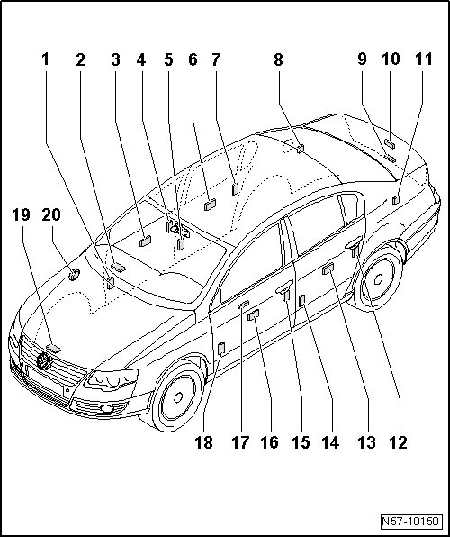
1 Coupling Station
• Installed location: right A-pillar
• To disconnect harness connector, release bellows at pillar, refer to=> [ Door ] Front Door
2 Comfort System Central Control Module (J393)
• Installed location: under the instrument panel on the front passenger side
3 Front Right Door Control Module
• Integrated in window regulator motor.
• Removing, refer to => [ Window Regulator Motor ] Front Door Window
4 Front Passenger Door Central Locking Lock Unit (F221)
• Door lock is secured to subframe.
• Electrical central locking system is integrated in door lock.
• Removing, refer to => [ Door Lock ] Door Components
5 Coupling Station
• Installed location: right B-pillar
• To disconnect harness connector, release bellows at pillar, refer to => [ Door ] Rear Door
6 Right Rear Door Control Module
• integrated in window regulator motor.
• Removing => [ Window Regulator Motor ] Service and Repair
7 Right Rear Central Locking Lock Unit (F223)
• Door lock is secured to subframe.
• Electrical central locking system is integrated in door lock.
• Removing:=> [ Door Lock ] Door Components
8 Fuel Tank Lid Unlock Motor (V155)
• Installed location: behind the luggage compartment trim panel on the right side
• Removing => [ Actuator ] Fuel Filler Door Unit
9 Rear Lid Handle Unlock Switch (E234)
• Installed location: inside the emblem
• Removing => [ Release Element ] Rear Lid
10 Rear Lid Lock
• Installed location: attached to the rear lid
• Removing and Installing, refer to => [ Rear Lid Lock ] Rear Lid
11 Rear Lid Coupling Station
• Installed location: behind the luggage compartment trim panel on the left side
12 Left Rear Central Locking Lock Unit (F222)
• Door lock is secured to subframe.
• Electrical central locking system is integrated in door lock.
• Removing, refer to=> [ Door Lock ] Door Components
13 Left Rear Door Control Module
• Integrated in window regulator motor.
• Removing, refer to => [ Window Regulator Motor ] Service and Repair
14 Coupling Station
• Installed location: left B-pillar
• To disconnect harness connector, release bellows at pillar, refer to => [ Door ] Rear Door
15 Driver Door Central Locking Lock Unit (F220)
• Door lock is secured to subframe.
• Electrical central locking system is integrated in door lock.
• Removing, refer to => [ Door Lock ] Door Components
16 Left Front Door Control Module
• Integrated in window regulator motor.
• Removing, refer to => [ Window Regulator Motor ] Front Door Window
17 Central Window Regulator Switch (in Driver door) (E189)
• Installed location: inside the door trim panel
18 Coupling Station
• Installed location: left A-pillar
• To disconnect harness connector, release bellows at pillar. Refer to => [ Door ] Front Door
19 Front Hood Switch (F266)
• Installed location: on the latch
• Removing and installing lid lock. Refer to => [ Hood Lock ] Hood
20 Alarm Horn (H12)
• Installed location: under the right fender
Remote Control Keys, Adapting
Adaptation of keys to remote control is performed using (VAS 5051 A).
- Select "Guided Fault Finding" on the vehicle diagnostic tester (VAS 5051 A).
- Using the Go to button, select "Function/Component selection" and the following menu items one after the other:
• Body
• Body - Repair work (Repair Groups 01 and 50 to 77)
• 01 - On Board Diagnostic capable systems
• Comfort system
• Functions - comfort system central control module
• J393 - adapt key with remote control
Remote Control Keys, Adapting to Immobilizer
Adaptation of keys to anti-theft immobilizer is performed using (VAS 5051 A).
- Select "Guided Fault Finding" on the vehicle diagnostic tester (VAS 5051 A).
- Using the Go to button, select "Function/Component selection" and the following menu items one after the other:
• Body
• Electrical Equipment (Repair Groups 01; 27; and 90 to 97)
• 01 - On Board Diagnostic capable systems
• Anti-Theft Immobilizer
• Anti-theft immobilizer functions
• Ignition key adaptation
Remote Control Key Assembly Overview
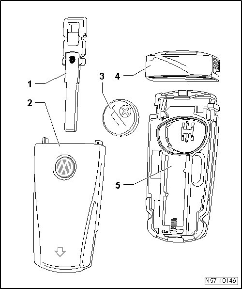
1 Emergency Key
2 Remote Control Key - Upper Section
3 Battery
• Removing and installing battery, refer to => [ Battery for Remote Control Key ] Central Locking.
4 Remote Control Key - Cover Cap
5 Remote Control Key with Variable Code Transponder - Lower Section