A/C Refrigerant System Component Overview
A/C Refrigerant System Component Overview
CAUTION!
Before beginning repairs on the electrical system:
• Obtain the anti-theft radio security code.
• Switch off all electrical consumers.
• Switch off ignition and remove ignition key.
• Disconnect negative ( - ) battery terminal.
• When disconnecting and reconnecting battery terminals, observe all applicable Notes and torque specifications, as well as instructions on performing OBD program and electrical system function checks as specified.
• Immediately plug open connections on A/C components to prevent dirt and moisture contamination.
• Before carrying out any work on the A/C refrigerant system, refer to A/C refrigerant system safety measures => [ Safety Precautions ] Safety Precautions.
• Except where indicated with * all system components illustrated must only be serviced or replaced after discharging refrigerant system.
• During servicing, all couplings, fittings and related fasteners must be torqued to specifications.
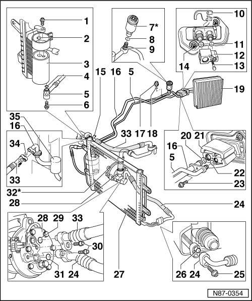
1 Sealing plug
• 15 Nm
2 O-ring
• 10.8 mm; 1.8 mm
3 Receiver drier
4 O-ring
• 10.8 mm; 1.8 mm
5 Refrigerant pipe
• From receiver drier to expansion valve
6 Bolt
• 15 Nm
7 A/C Pressure Switch (F129) (4-Pin) or High Pressure Sensor (G65) (3-Pin)
• Depending on engine type, refrigerant systems have either an A/C Pressure Switch (F129) or High Pressure Sensor (G65) installed. Refer to appropriate wiring diagram.
• A/C Pressure Switch (F129), checking => [ A/C Pressure Switch, Checking ] A/C Pressure Switch, Checking
• High Pressure Sensor (G65), function => [ High Pressure Sensor, Function ] High Pressure Sensor, Function, multi-pin connector assignments => [ High Pressure Sensor, Multi-Pin Connector Assignments ] High Pressure Sensor, Multi-Pin Connector Assignments, electrical checks => [ High Pressure Sensor, Electrical Testing ] High Pressure Sensor, Electrical Testing.
• Removing and installing => [ A/C Pressure Switch and High Pressure Sensor ] Service and Repair
• Component can be removed without discharging refrigerant system
8 O-ring
• 10.8 mm; 1.8 mm
9 Refrigerant pipe
10 Threaded plate
11 O-ring
• 10.8 mm; 1.8 mm
12 Expansion valve
13 Bolt
• 8 Nm
14 O-ring
• 14 mm; 1.8 mm
15 High pressure service valve
• Only use Kent Moore ACR4 or equivalent
16 Refrigerant pipe
17 Low pressure service valve
• Only use Kent Moore ACR4 or equivalent
18 O-ring
• 7,6 mm; 1.8 mm
19 Evaporator
• In heater/evaporator unit
• Removing => [ Heater/Evaporator Unit ] Heater / Evaporator Unit, heater/evaporator unit, disassembly and assembly
20 O-ring
• 16.7 mm; 1.8 mm
21 Insulation
22 O-ring
• 7,6 mm; 1,8 mm
23 Bolt
• 8 Nm
24 Refrigerant hose
• From compressor to condenser
25 Bolt
• 15 Nm
26 O-ring
• 10.8 mm; 1.8 mm
27 Condenser
• Removing and installing => [ Condenser ] Service and Repair
28 Compressor
• Sanden SD7-V16
• Removing and installing compressor bracket => [ Description and Operation ] Description and Operation
29 O-ring
• 14.3 mm; 2.4 mm
30 Bolt
• 20 Nm
31 O-ring
• 10.8 mm; 1.8 mm
32 A/C Clutch (N25)
• Sanden
• Servicing => [ A/C Clutch, Sanden Assembly Overview ] A/C Clutch, Sanden Assembly Overview.
33 Refrigerant hose
34 O-ring
• 10.8 mm; 1.8 mm
35 Damper