Function 08 - Read Measuring Value Block
Function 08 - Read Measuring Value Block
The measuring value block is divided into 4 display group numbers. Each display group contains individual display fields => [ Read Measuring Value Block Display Groups, Interpreting ] Read Measuring Value Block Display Groups, Interpreting.
Use this function to observe various instrument cluster inputs.
- Connect scan tool (VAG 1551) , input address word 19 "Gateway" and then press -> button until "Select function XX" is shown in display
Indicated on display:
Rapid data transfer HELP
Select function XX
- Press buttons 0 and 8 to select function " Read measuring value block".
Indicated on display:
Rapid data transfer Q
08 - Read Measuring Value Block
- Press Q button to confirm input.
Indicated on display:
Read Measuring Value Block Help
Enter display group number XXX
- Using the scan tool button pad, enter the required display group number (following example shows display group 001).
- Press Q button to confirm input.
Indicated on display: (1...4 = Display fields)
Read Measuring Value Block 1 ->
1 2 3 4
• Interpreting display groups and evaluating measured values in individual display fields => tables beginning => [ Read Measuring Value Block Display Groups, Interpreting ] Read Measuring Value Block Display Groups, Interpreting.
• With the printer switched on, the information on the display is printed out.
• To easily change between display groups, proceed as follows:
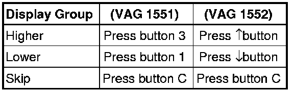
- Displayed after pressing C button.
Indicated on display:
Read Measuring Value Block Help
Enter display group number XXX
- Enter alternate display group number as needed => tables beginning => [ Read Measuring Value Block Display Groups, Interpreting ] Read Measuring Value Block Display Groups, Interpreting.
• Display fields always show actual values transmitted from senders and sensors. However, instrument cluster display values can differ from those in the display fields due to internal filtering.
• Other display groups are possible, but are not required for on board diagnostic program!
The condition of the data-bus function for control modules which are connected to the power-train data-bus is displayed in display groups 125 and 126.
The display fields for control modules which are not installed remain empty.