Emission Control Systems: Diagrams
Vacuum Hose Setup at Intake Manifold, Assembly Overview
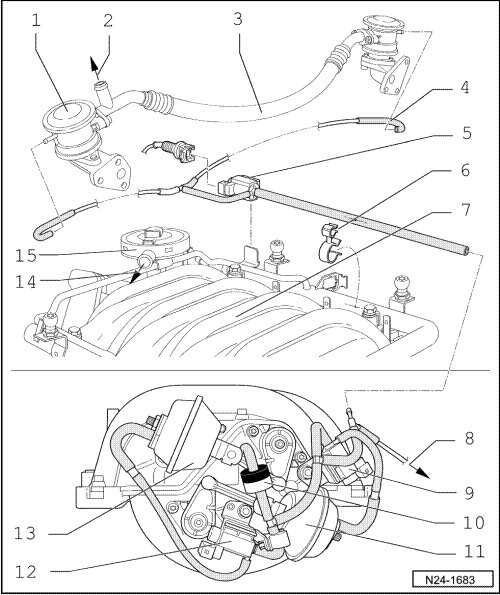
1 Combi-valve
• For secondary air injection
2 To Secondary Air Injection (AIR) Pump Motor (V101)
3 Connecting hose
• Route tension-free
4 Vacuum connection
• For combination-valve
5 Secondary air injection (AIR) solenoid valve (N112)
• Secured to fuel rail
6 Bracket
• Secured to fuel rail
7 Intake manifold change-over
8 To vacuum reservoir
• --> [ (Item 10) To vacuum reservoir ] Secondary Air Injection System, Assembly Overview
9 Intake Manifold Tuning (IMT) Valve 2 (N261)
10 Non-return valve
• Black side of valve faces intake manifold connection
11 Vacuum actuator
• For variable intake manifold
12 Intake Manifold Tuning (IMT) Valve (N156)
13 Vacuum actuator
• For variable intake manifold
14 To cylinder block
• --> [ (Item 3) Connecting hose ] Part II - Cylinder Block, Assembly Overview
15 Crankcase vent valve