Variable Valve Timing Actuator: Testing and Inspection
Diagnostic Procedures
Camshaft Adjusting Valves, Checking
The camshaft adjustment is load- and RPM dependent. The electrical valves for camshaft adjustment switch oil pressure onto camshaft adjusters (mechanical adjustment mechanisms), which then adjust the camshafts.
Special tools, testers and auxiliary items required
• Multimeter (VAG1526) or multimeter (VAG1715)
• Connector test kit (VAG1594)
• Wiring diagram
Test requirements
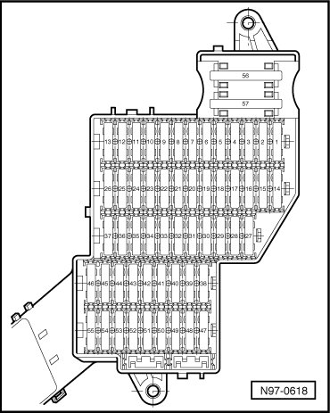
• Respective fuses of camshaft adjustment valves in fuse box (instrument panel, left) must be OK:
• Ignition switched off.
Test sequence
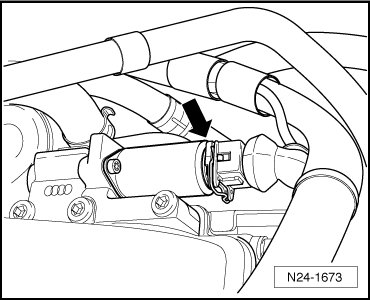
Cylinder bank 1
- Disconnect 2-pin connector from Valve -1- for camshaft adjustment (N205) (arrow).
Cylinder bank 2
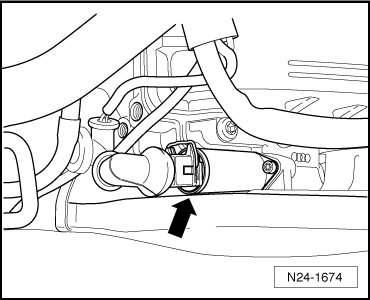
- Disconnect 2-pin connector from Valve -2- for camshaft adjustment (N208) (arrow).
Cylinder bank 1 and 2
• Cylinder bank 1 = in direction of travel, right.
• Cylinder bank 2 = in driving direction, left.
Checking resistances
- Measure resistance between terminals of the respective valve for camshaft adjustment.
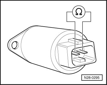
Specified value: 10.0 to 18.0 ohms
If specified value is not obtained:
- Replace the camshaft adjuster with the respective Valve -1- for camshaft adjustment (N205) / Valve -2- for camshaft adjustment (N208):
- Erase DTC memory of Engine Control Module (ECM) , Diagnostic mode 4: Reset/erase diagnostic data.
- Generate readiness code.
If specified value is obtained:
- Check wires according to wiring diagram.
Checking wiring
- Connect test box to control module wiring harness , connect test box for wiring test.
- Check wires between test box and 2-pin connector to Engine Control Module (ECM) for open circuit according to wiring diagram.
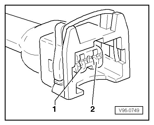
Wire resistance: max. 1.5 ohms
Cylinder bank 1

Cylinder bank 2

Cylinder bank 1 and 2
- Also check wires for short circuit to B+ or Ground (GND).
Specified value: infinite ohms
- Check wire between 2-pin connector terminal 1 and Motronic Engine Control Module (ECM) Power Supply Relay (J271) for open circuit according to wiring diagram.
Wire resistance: max. 1.5 ohms
- Erase DTC memory of Engine Control Module (ECM) , Diagnostic mode 4: Reset/erase diagnostic data.
- Generate readiness code.
If no malfunctions are detected in the wires and the resistance value is OK:
- Replace Motronic Engine Control Module (ECM) (J220).