Fuel Pump, Checking
Diagnostic Procedures
Fuel Pump, Checking
Test requirements
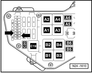
• Fuses - 13 - and - 14 - (arrows) in E-box (plenum chamber, left) must be OK:
• Fuel Pump (FP) relays I and II must be OK:
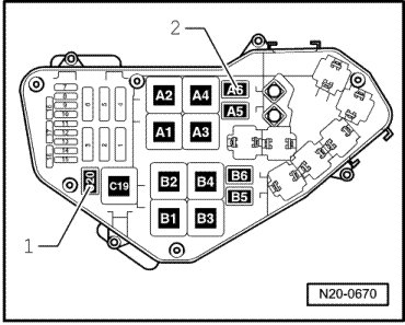
1. Fuel Pump (FP) Relay (J17), (Fuel Pump, right)
2. Fuel Pump (FP) 2 Relay (J49), (Fuel Pump, left)
• Battery voltage must be at least 11.5 volts.
• All electrical consumers such as, for example, lights and rear window defroster must be switched off.
• For vehicles with automatic transmission, selector lever must be in P.
• Parking brake must be engaged or else daylight driving lights will be switched on.
• Ignition switched off.
Observe Safety Precautions.
Observe Clean Working Conditions.
Check function and voltage supply of fuel pumps.
Check delivery quantity, current pick-up, and check valves of Fuel Pumps (FP).
Checking function and voltage supply of fuel pumps
Special tools, testers and auxiliary items required
• Multimeter (VAG1526) or multimeter (VAG1715)
• Connector test kit (VAG1594)
• Wiring diagram
Test sequence, Fuel Pump (FP) (G6), right
Test sequence, Transfer Fuel Pump (FP) (G23), left
- Remove Fuel Pump (FP) Relay (J17), right, from relay carrier, position C20.
• Do not use metallic tools to pry off relays from relay carrier. The terminals could conduct electricity.
- Bridge terminals 19d + 19e on relay carrier using appropriate adapter cables.
- Switch ignition on.
Fuel Pump (FP) (G6), right, must start up.
- Switch ignition off.
If Fuel Pump (FP) runs:
- Check activation of Fuel Pump (FP) Relay (J17), right, - 1 - according to wiring diagram:
- Erase DTC memory of Engine Control Module (ECM) , Diagnostic mode 4: Reset/erase diagnostic data.
- Generate readiness code.
If Fuel Pump (FP) does not run:
- Remove bridge from terminal 19e.
- Connect multimeter to terminal 19e + Ground (GND) of relay socket for voltage measurement.
- Switch ignition on.
Specified value: at least 11.5 V
- Switch ignition off.
If specified value is not obtained:
- Locate and repair open circuit using wiring diagram:
- Erase DTC memory of Engine Control Module (ECM) , Diagnostic mode 4: Reset/erase diagnostic data.
- Generate readiness code.
If specified value is obtained:
- Bridge terminals 19d + 19e on relay carrier using appropriate adapter cables.
- Disconnect 4-pin harness connector (arrow) left, next to fuel tank, at vehicle floor.
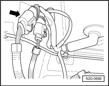
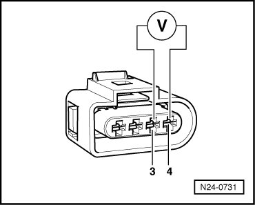
- Connect multimeter to terminals 3 + 4 of connector for voltage measurement.
- Switch ignition on.
Specified value: at least 11.5 V
- Switch ignition off.
If specified value is not obtained:
- Locate and repair open circuit using wiring diagram:
- Erase DTC memory of Engine Control Module (ECM) , Diagnostic mode 4: Reset/erase diagnostic data.
- Generate readiness code.
If specified value is obtained:
- Fuel Pump (FP) (G6) faulty, replace Fuel Pump (FP) unit , Fuel Pump (FP) unit, fuel gauge sender, and suction jet pump, removing and installing.
- Erase DTC memory of Engine Control Module (ECM) , Diagnostic mode 4: Reset/erase diagnostic data.
- Generate readiness code.
Test sequence, Transfer Fuel Pump (FP) (G23), left
- Remove Fuel Pump (FP) 2 Relay (J49), left, from relay carrier, position A6.
• Do not use metallic tools to pry off relays from relay carrier. The terminals could conduct electricity.
- Bridge terminals 6d + 6e on relay carrier using appropriate adapter cables.
- Switch ignition on.
Transfer Fuel Pump (FP) (G23), left, must start up.
- Switch ignition off.
If Fuel Pump (FP) runs:
- Check activation of Fuel Pump (FP) 2 Relay (J49), left, - 2 - according to wiring diagram:
- Erase DTC memory of Engine Control Module (ECM) , Diagnostic mode 4: Reset/erase diagnostic data.
- Generate readiness code.
If Fuel Pump (FP) does not run:
- Remove bridge from terminal 6e.
- Connect multimeter to terminal 6e + Ground (GND) of relay socket for voltage measurement.
- Switch ignition on.
Specified value: at least 11.5 V
- Switch ignition off.
If specified value is not obtained:
- Locate and repair open circuit using wiring diagram:
- Erase DTC memory of Engine Control Module (ECM) , Diagnostic mode 4: Reset/erase diagnostic data.
- Generate readiness code.
If specified value is obtained:
- Bridge terminals 6d + 6e on relay carrier using appropriate adapter cables.
- Disconnect 4-pin harness connector (arrow) left, next to fuel tank, at vehicle floor.
- Connect multimeter to terminals 1 +2 of connector for voltage measurement.
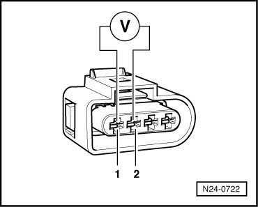
- Switch ignition on.
Specified value: at least 11.5 V
- Switch ignition off.
If specified value is not obtained:
- Locate and repair open circuit using wiring diagram:
- Erase DTC memory of Engine Control Module (ECM) , Diagnostic mode 4: Reset/erase diagnostic data.
- Generate readiness code.
If specified value is obtained:
- Transfer Fuel Pump (FP) (G23), left, faulty, replace Fuel Pump (FP) unit , Fuel Pump (FP) unit, fuel gauge sender, and suction jet pumps, removing and installing.
- Erase DTC memory of Engine Control Module (ECM) , Diagnostic mode 4: Reset/erase diagnostic data.
- Generate readiness code.
Checking delivery quantity, current pick-up, and check valves of Fuel Pumps (FP)
Test requirement
• Function and voltage supply of fuel pumps OK
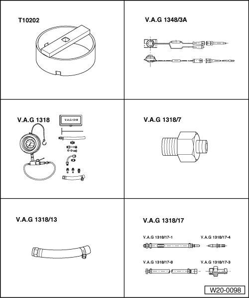
Special tools, testers and auxiliary items required
• Wrench (T10202)
• Remote control (VAG1348/3A) with adapter cable (VAG1348/3-3)
• Pressure gauge (VAG1318)
• Adapter (VAG1318/7)
• Adapter (VAG1318/13)
• Adapter (VAG1318/17)
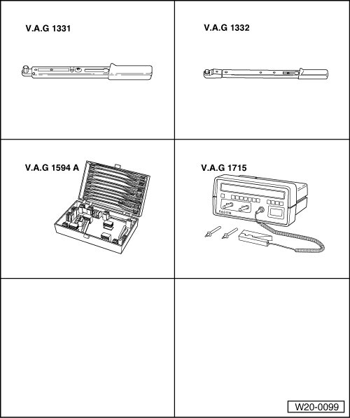
Special tools, testers and auxiliary items required
• Torque wrench (5 to 50 Nm) (VAG1331)
• Torque wrench (40 to 200 Nm) (VAG1332)
• Connector test kit (VAG1594A)
• Multimeter (VAG1715)
without illustration:
• Measuring container
• Wiring diagram
Checking fuel delivery
- Remove fuel filler cap from fuel filler tube.
First, reduce fuel pressure as follows:
CAUTION!
• The fuel or fuel lines in fuel system can become very hot (danger of scalding)!
• In addition, the fuel system is under pressure!Before opening the system, place rags around the connection area and release pressure by carefully loosening the connection!
• Wear protective goggles and protective gloves when working on the fuel system!
- Place a rag around separating point to catch escaping fuel.
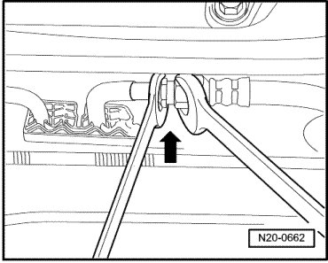
- Remove fuel supply line (arrow).
When the fuel pressure is reduced:
- Tighten threaded connection again.
Checking fuel delivery:
• Fuel Pump (FP) (G6), right ,
• Transfer Fuel Pump (FP) (G23), left ,
• Fuel Pumps (FP) left and right.
Supply quantity of Fuel Pump (FP) (G6), right, checking
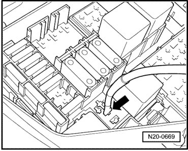
- Connect remote control (VAG1348/3A) to connector (arrow) of Fuel Pump (FP) relay for right Fuel Pump (FP) using adapter (VAG1348/3-3).
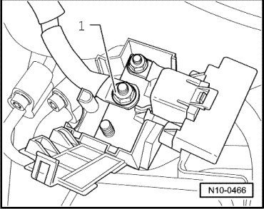
- Connect alligator of remote control to B+ connection - 1 -.
- Disconnect fuel supply line - 1 - from fuel distributor.
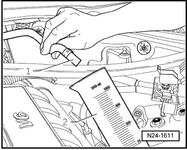
- Place hose in a measuring container - 2 - of at least 1000 cm3.
- Measuring container must be emptied before measurement.
- Operate remote control
15 seconds:a minimal delivery quantity of
800 cm3/15 seconds must be obtained.
Supply quantity of Transfer Fuel Pump (FP) (G23), left, checking
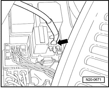
- Connect remote control (VAG1348/3A) to connector (arrow) of Fuel Pump (FP) relay for left Fuel Pump (FP) using adapter (VAG1348/3-3).
- Connect alligator of remote control to B+ connection - 1 -.
- Disconnect fuel supply line - 1 - from fuel distributor.
- Place hose in a measuring container - 2 - of at least 1000 cm3.
- Measuring container must be emptied before measurement.
- Operate remote control
15 seconds:a minimal delivery quantity of
800 cm3/15 seconds must be obtained.
Supply quantity of both Fuel Pumps (FP), checking
- For this, now connect adapter (VAG1348/3-3) of remote control to connector of Fuel Pump (FP) Relay, left and right:
• Connector (arrow) of Fuel Pump (FP) Relay for right Fuel Pump (FP).
• Connector (arrow) of Fuel Pump (FP) Relay for left Fuel Pump (FP).
- Connect alligator of remote control to B+ connection - 1 -.
- Disconnect fuel supply line - 1 - from fuel distributor.
- Place hose in a measuring container - 2 - of at least 1000 cm3.
- Measuring container must be emptied before measurement.
- Operate remote control
10 seconds:a minimal delivery quantity of
800 cm3/10 seconds must be obtained.
If the minimal delivery quantity is not obtained during one of the tests:
- Check fuel lines for possible restrictions (kinks) or clogging.
If the lines are OK:
- Replace filter element in fuel filter.
- Erase DTC memory of Engine Control Module (ECM) , Diagnostic mode 4: Reset/erase diagnostic data.
- Generate readiness code.
Delivery rate has been obtained, but malfunctions are still suspected in the fuel supply (e.g. sporadic loss of fuel supply):
- Check current pick-up of Fuel Pumps (FP)
Checking current pick-up of Fuel Pumps (FP)
Check current pick-up of each individual Fuel Pump (FP) as follows:
- Re-connect all disconnected fuel lines.
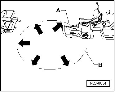
- Cut through floor carpet from point - A - to point - B - in pre-cut area (arrows).
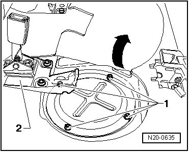
- Unscrew nuts - 1 - of cover. Remove backrest support - 2 - or mounting bracket if necessary.
- Connect multimeter with electrical current probe to wire of 4-pin connector terminal - 1 - (arrow) from wiring harness to Fuel Pump (FP), right.
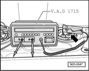
- Start engine and let run at idle.
- Measure Fuel Pump (FP) current draw.
Specified value: max. 11 amperes
If current draw is exceeded:
- Fuel Pump (FP), right, faulty, replace Fuel Pump (FP) unit , Fuel Pump (FP) unit, fuel gauge sender, and suction jet pumps, removing and installing.
- Erase DTC memory of Engine Control Module (ECM) , Diagnostic mode 4: Reset/erase diagnostic data.
- Generate readiness code.
- Repeat test on Fuel Pump (FP), left.
If current draw is exceeded:
- Fuel Pump (FP), left, faulty, replace Fuel Pump (FP) unit , Fuel Pump (FP) unit, fuel gauge sender, and suction jet pumps, removing and installing.
- Erase DTC memory of Engine Control Module (ECM) , Diagnostic mode 4: Reset/erase diagnostic data.
- Generate readiness code.
• If malfunction in fuel system is sporadic, test can also be performed during a road test, but a second person is required.