Disassembly and Assembly
Heater/Evaporator Housing Disassebly
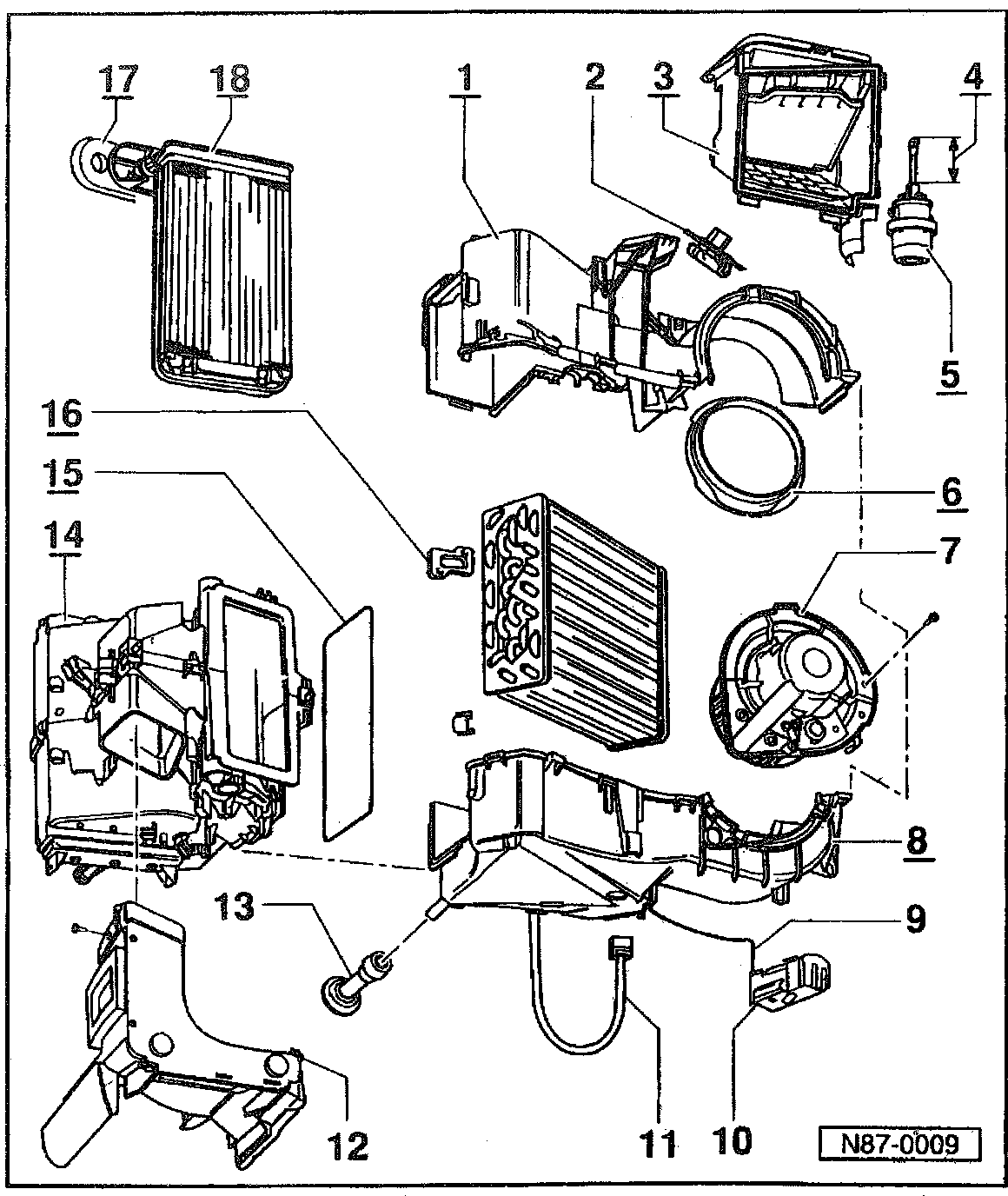
1 Upper evaporator housing
• Seal gooves and contact surfaces with silicone rubber sealant Part No. AKD 476 KD5 05 or equivalent
2 Fresh air blower series resistance with fuse - N24
3 Intake duct
• Glue seal to ensure water tight connection
4 Fresh air/recirculation flap vacuum servo
6 Air intake ring
7 Fresh air blower - V2
8 Lower evaporator housing
• Seal grooves and contact surfaces with silicone rubber sealant Part No. AKD 476 KD5 05 or equivalent
9 A/C evaporator temperature switch -E33- sensing tube
10 A/C evaporator temperature switch - E33
• Insert sensing tube of temperature switch into evaporator 330 mm (13.0 in.)
• Replaceable only with cover and insulation
• Prevents evaporator from freezing
• Not needed on vehicles with variable displacement, self regulating compressors (these compressors will not allow evaporator temperatures to drop below freezing)
11 Retainging strap
• Replace with Part No. 191 820 845
12 Footwell vent
13 Evaporator water drain valve
• Install with lip facing down
• Remove and dirt or undercoating from valve
• Press fit onto lower evaporator housing (not glued)
14 Air distribution housing
• Flaps cannot be replaced individually
15 Seal (round)
• Must be water tight
16 Seal
• Must be water tight
17 Seal
• Must be water tight
18 Heater core
• If heater core is replaced drain entire cooling system and refill with new coolant