Mixture Calibration Potentiometer: Testing and Inspection
Fig 12 CO Potentiometer:
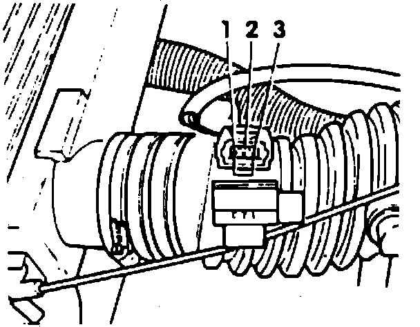
1. Ensure battery voltage is correct, all ground connections are satisfactory and air conditioning is off.
2. On Corrado models, fuses 16, 18 and 21 and on all other models, fuses 3, 5 and 18 are OK.
3. Connect scan tool tester No. VAG 1551 or equivalent, as follows:
a. Remove shifter tunnel cover, then connect black connector to black test connector.
b. Connect white connector to white test connector.
c. Blue connector is not used.
4. Start engine and allow to idle, ensure coolant temperature is 176°F minimum.
5. Select ``Read measuring value block,'' then select the following in order:
a. 1-``Rapid data transfer.''
b. 01-``Engine electronics.''
c. 08-``Read measuring value block.''
6. Press 0 keys twice to select ``Display group No. 00.''
7. Press Q key to enter input and observe display value on channel 2.
8. If display value is 40--140, CO potentiometer and triggering is OK.
9. If display value is 0--2, there is a short in negative wire or defective CO potentiometer and control unit, proceed as follows:
a. Disconnect CO potentiometer harness connector. Display value should be a minimum of 250. If reading signal to potentiometer is OK.
b. Turn off ignition, then replace potentiometer assembly.
c. Clear trouble code memory as described in the ``Computerized Engine Controls'' section, then check idle speed and CO content. Display value must be 0--2.
d. If display value is greater than 250, signal to CO potentiometer is faulty.
e. Check for short in wiring from control unit to ground.
f. If circuit is satisfactory, replace control unit, then clear trouble code memory as described in the ``Computerized Engine Control'' section.
10. If display value is a minimum of 250, an open circuit in wiring between potentiometer and control unit is present. Perform the following test:
a. Disconnect CO potentiometer harness connector, then bridge terminals 1 and 3 of connector using jumper wires from VW 1594 adapter kit, Fig 12.
b. Display value must read 0--2.
c. If within specifications, control unit signal is OK.
d. With ignition switch off, replace CO potentiometer assembly.
e. Clear trouble code memory as described in the ``Computerized Engine Controls'' section, then check idle speed and CO content, adjust if necessary. Display value must be a greater than 250.
f. If display value is not greater than 250, control unit signal is faulty.
g. With ignition off, reconnect CO potentiometer harness connector.
h. Check for open circuit. If not found, replace control unit, then activate and clear trouble code memory as described in the ``Computerized Engine Controls'' section.