Reassembly
HEATING / AIR CONDITIONING: AIR CONDITIONING UNIT: REASSEMBLY
1. INSTALL NO. 1 COOLER THERMISTOR Installation
2. INSTALL NO. 1 COOLER EVAPORATOR SUB-ASSEMBLY
(a) Sufficiently apply compressor oil to 2 new O-rings and the fitting surfaces.
Compressor oil:
ND-OIL 11 or equivalent
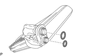
(b) Install the 2 O-rings to the No. 1 cooler evaporator sub-assembly.
NOTICE:
* Keep the O-rings and O-ring fitting surfaces free from dirt or any foreign objects.
* Do not use any compressor oil other than ND-OIL 11 or equivalent. If any compressor oil other than ND-OIL 11 or equivalent is used, compressor motor insulation performance may decrease, resulting in a leakage of electric power.
(c) Engage the clamp and install the No. 1 cooler evaporator sub-assembly with the No. 1 cooler thermistor.
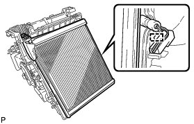
HINT
Completely cover the tube with the grommet.
(d) Engage the 4 claws.
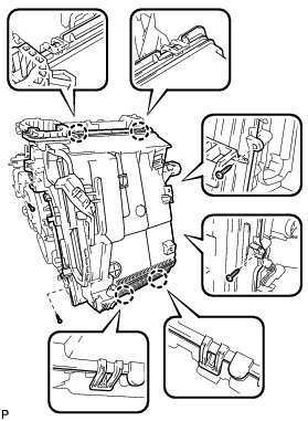
(e) Install the lower heater case with the 4 screws.
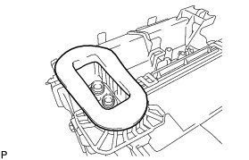
(f) Install the packing.
3. INSTALL COOLER EXPANSION VALVE
(a) Using a 4 mm hexagon wrench, install the cooler expansion valve with the 2 hexagon bolts.
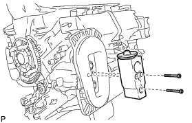
Torque : 3.5 Nm (36 kgf-cm, 31 in-lbf)
4. INSTALL DRAIN COOLER HOSE
(a) Install the drain cooler hose as shown in the illustration.
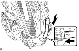
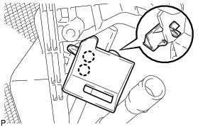
5. INSTALL CONSOLE MOUNTING BRACKET RH
(a) Engage the 2 claws and install the console mounting bracket RH.
6. INSTALL AIR CONDITIONING AMPLIFIER ASSEMBLY
(a) Engage the 2 guides to install the air conditioning amplifier assembly as shown in the illustration.
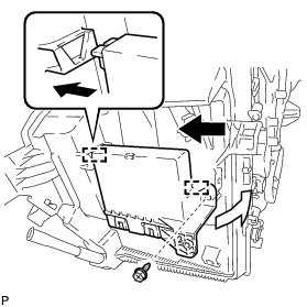
(b) Install the screw.
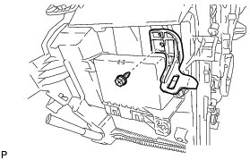
7. INSTALL CONSOLE MOUNTING BRACKET LH
(a) Install the console mounting bracket LH with the screw.
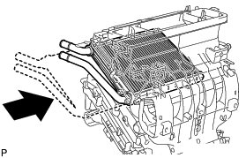
8. INSTALL HEATER RADIATOR UNIT SUB-ASSEMBLY
(a) Install the heater radiator unit sub-assembly as shown in the illustration.
(b) Install the clamp with the screw.
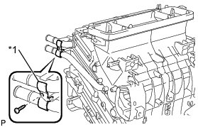
Text in Illustration
9. INSTALL QUICK HEATER ASSEMBLY Installation
10. INSTALL AIR MIX CONTROL SERVO MOTOR SUB-ASSEMBLY
(a) Using the reference point, install the air mix control servo motor sub-assembly with the 3 screws.
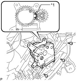
Text in Illustration

11. INSTALL AIR OUTLET CONTROL SERVO MOTOR SUB-ASSEMBLY
(a) Using the reference point, install the air outlet control servo motor sub-assembly with the 3 screws.
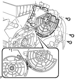
Text in Illustration