Cylinder Head Assembly
CYLINDER HEAD SUB-ASSEMBLYThe cylinder head bolts are tightened in 2 progressive steps.
Using several steps, uniformly install and tighten the 10 cylinder head set bolts and plate washers with a 10 mm bi-hexagon wrench in the order shown in the illustration.
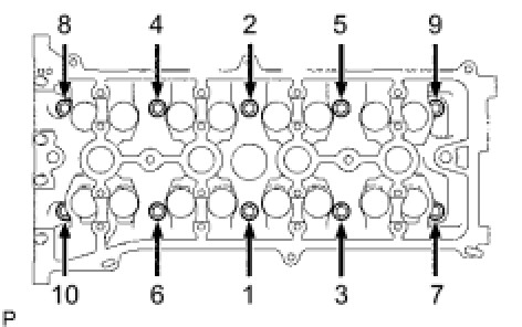
Torque 70 Nm (714 kgf-cm, 52 ft-lbf)
Mark the front side of the cylinder head bolts with paint.
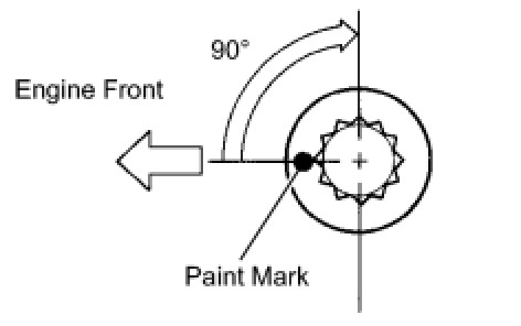
Retighten the cylinder head bolts 90° in the sequence shown in the illustration.
Check that the paint mark is now at a 90° angle from the front.
CYLINDER HEAD SET BOLT
Standard bolt length 141.3 to 142.7 mm (5.563 to 5.618 in.)
Maximum bolt length 144.2 mm (5.677 in.)
SURFACE VARIATION

CAMSHAFT ()
Using several steps, uniformly tighten the 10 bearing cap bolts in the sequence shown in the illustration.
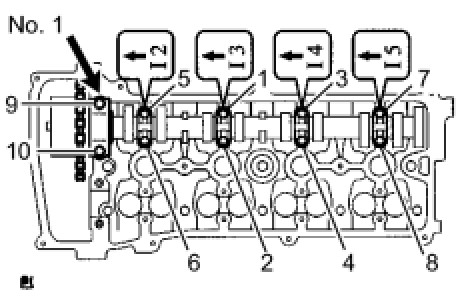
No. 1 bearing cap - Torque 30 Nm (301 kgf-cm, 22 ft-lbf)
No. 3 bearing cap - Torque 9.0 Nm (92 kgf-cm, 80 in-lbf)
NO. 2 CAMSHAFT
Using several steps, uniformly tighten the 10 bearing cap bolts in the sequence shown in the illustration.
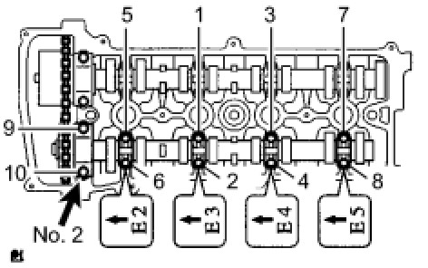
No. 2 bearing cap - Torque 30 Nm (301 kgf-cm, 22 ft-lbf)
No. 3 bearing cap - Torque 9.0 Nm (92 kgf-cm, 80 in-lbf)
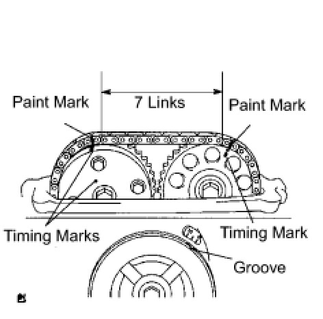
Check that the paint marks on the chain are aligned with the timing marks on the camshaft timing gear and camshaft timing sprocket. Also, check that the crankshaft pulley groove is aligned with the timing mark "0" of the timing chain cover.
CAMSHAFT ()
Using several steps, uniformly tighten the 20 bearing cap bolts in the sequence shown in the illustration.
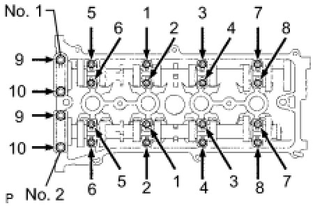
No. 1 and No. 2 bearing cap - Torque 30 Nm (301 kgf-cm, 22 ft-lbf)
No. 3 bearing caps - Torque 9.0 Nm (92 kgf-cm, 80 in-lbf)
INTAKE MANIFOLD TORQUE & SEQUENCE Specifications
EXHAUST MANIFOLD TORQUE & SEQUENCE Specifications
CAMSHAFT GEAR/SPROCKET TORQUE Specifications