Engine Unit, Inspection
INSPECTION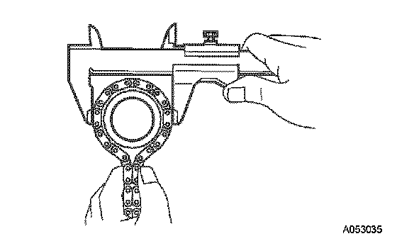
1. INSPECT OIL PUMP DRIVE SPROCKET
a. Wrap the chain around the drive sprocket.
b. Using a vernier caliper, measure the drive sprocket diameter with the chain.
NOTICE: The vernier caliper must contact the chain rollers for the measurement.
Minimum sprocket diameter (w/ chain): 48.2 mm (1.898 inch)
If the diameter is less than the minimum, replace the chain and sprocket.
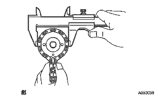
2. INSPECT OIL PUMP DRIVEN SPROCKET
a. Wrap the chain around the driven sprocket.
b. Using a vernier caliper, measure the driven sprocket diameter with the chain.
NOTICE: The vernier caliper must contact the chain rollers for the measurement.
Minimum sprocket diameter (w/ chain): 48.2 mm (1.898 inch)
If the diameter is less than the minimum, replace the chain and drive shaft gear.
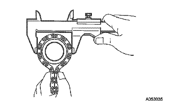
3. INSPECT CRANKSHAFT TIMING GEAR OR SPROCKET
a. Wrap the chain around the timing sprocket.
b. Using a vernier caliper, measure the timing sprocket diameter with the chain.
NOTICE: The vernier caliper must contact the chain rollers for the measurement.
Minimum sprocket diameter (w/ chain): 51.6 mm (2.031 inch)
If the diameter is less than the minimum, replace the chain and timing gear.
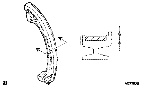
4. INSPECT CHAIN TENSIONER SLIPPER
a. Measure the tensioner slipper wear.
Maximum wear: 1.0 mm (0.039 inch)
If the wear is greater than the maximum, replace the tensioner slipper.
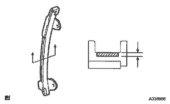
5. INSPECT CHAIN VIBRATION DAMPER NO.1
a. Measure the vibration damper wear.
Maximum wear: 1.0 mm (0.039 inch)
If the wear is greater than the maximum, replace the vibration damper.
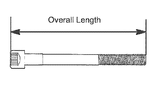
6. INSPECT CYLINDER HEAD SET BOLT
a. Using a vernier caliper, measure the length of the head bolts from the seat to the end.
Specified bolt length: 161.3 to 164.2 mm (6.350 to 6.465 inch)
If the length is greater than the maximum, replace the bolt.
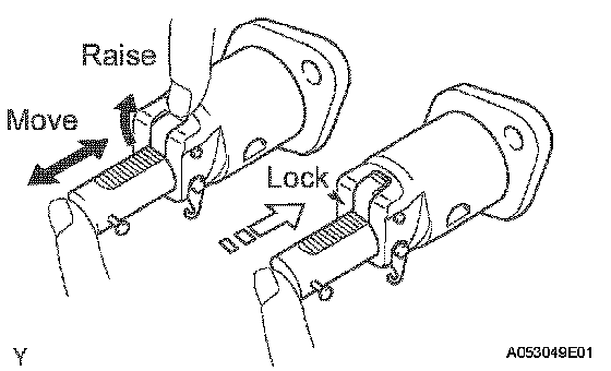
7. INSPECT NO.1 CHAIN TENSIONER ASSEMBLY
a. Check that the plunger moves smoothly when the ratchet pawl is raised.
b. Release the ratchet pawl and check that the plunger is locked in place by the ratchet pawl and does not move when pushed.
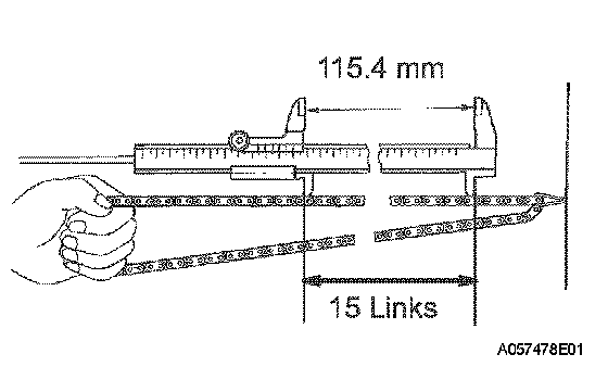
8. INSPECT CHAIN SUB-ASSEMBLY
a. Using a vernier caliper, measure the length of 15 links with the chain fully stretched.
Maximum chain elongation: 115.4 mm (4.543 inch)
If the elongation is greater than the maximum, replace the chain.
NOTICE: Make the same measurements pulling at 3 or more places selected at random. Average the measurements.
9. INSPECT CAMSHAFT TIMING GEAR OR SPROCKET
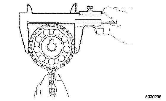
a. Wrap the chain around the timing sprocket.
b. Using a vernier caliper, measure the timing sprocket diameter with the chain.
Minimum sprocket diameter (w/chain): 97.3 mm (3.831 inch)
If the diameter is less than the minimum, replace the chain and timing gear.
NOTICE: The vernier caliper must contact the chain rollers for the measurement.
10. INSPECT CAMSHAFT
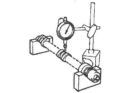
a. Check the camshaft for runout.
1 Place the camshaft on V-blocks.
2 Using a dial indicator, measure the circle runout at the center journal.
Maximum circle runout: 0.03 mm (0.0012 inch)
If the circle runout is greater than the maximum, replace the camshaft.
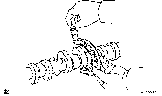
b. Using a micrometer, measure the cam lobe height.
Specified cam lobe height: 46.599 to 46.809 mm (1.8346 to 1.8429 inch)
If the cam lobe height is less than the minimum, replace the camshaft.
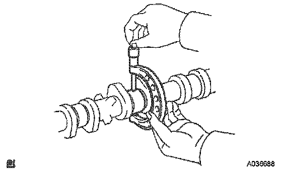
c. Using a micrometer, measure the journal diameter.
No. 1 journal diameter: 35.971 to 35.985 mm (1.4162 to 1.4167 inch)
Other journal diameter: 22.959 to 22.975 mm (0.9039 to 0.9045 inch)
If the journal diameter is not as specified, check the oil clearance.
11. INSPECT NO.2 CAMSHAFT
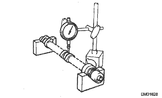
a. Check the camshaft for runout.
1 Place the camshaft on V-blocks.
2 Using a dial indicator, measure the circle runout at the center journal.
Maximum circle runout: 0.03 mm (0.0012 inch)
If the circle runout is greater than the maximum, replace the camshaft.
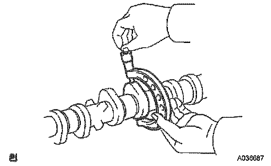
b. Using a micrometer, measure the cam lobe height.
Specified cam lobe height: 45.599 to 46.809 mm (1.8346 to 1.8429 inch)
If the cam lobe height is less than the minimum, replace the camshaft.
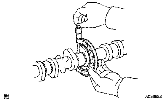
c. Using a micrometer, measure the journal diameter.
No. 1 journal diameter: 35.971 to 35.985 mm (1.4162 to 1.4167 inch)
Other journal diameter: 22.959 to 22.975 mm (0.9039 to 0.9045 inch)
If the journal diameter is not as specified, check the oil clearance.
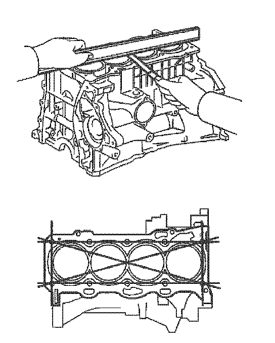
12. INSPECT CYLINDER BLOCK FOR FLATNESS
a. Using a precision straight edge and feeler gauge, measure the surface contacting the cylinder head gasket for warpage.
Maximum warpage: 0.05 mm (0.0020 inch)
If the warpage is greater than the maximum, replace the cylinder block.
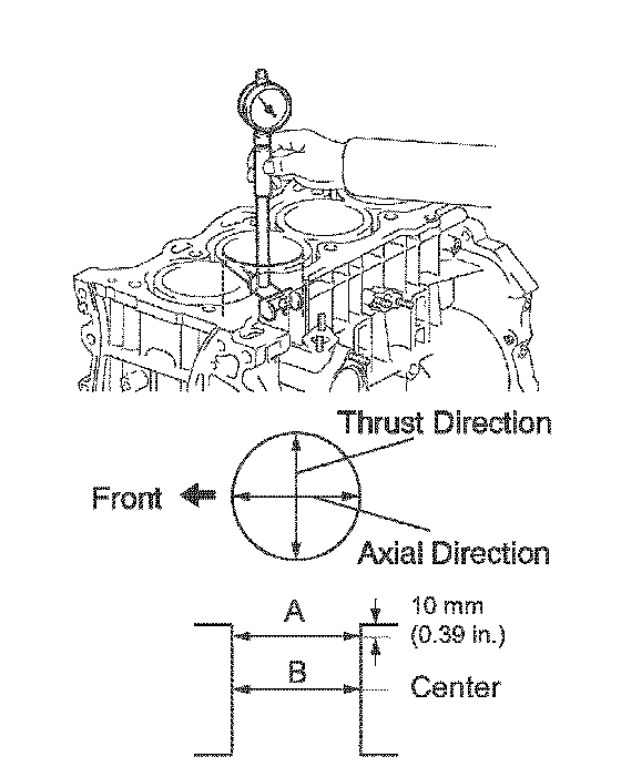
13. INSPECT CYLINDER BORE
a. Using a cylinder gauge, measure the cylinder bore diameter at positions A and B in the thrust and axial directions.
Specified diameter: 88.500 to 88.633 mm (3.4843 to 3.4894 inch)
If the diameters is greater than the maximum, replace the cylinder block.
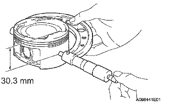
14. INSPECT PISTON DIAMETER
a. Using a micrometer, measure the piston diameter at right angles to the piston pin center line, 30.3 mm (1.193 inch) from the piston head.
Piston diameter: 88.439 to 88.449 mm (3.4818 to 3.4822 inch)
15. INSPECT PISTON CLEARANCE
a. Subtract the piston diameter measurement from the cylinder bore diameter measurement.
Specified oil clearance: 0.051 to 0.100 mm (0.0020 to 0.0039 inch)
If the clearance is greater than the maximum, replace all the 4 pistons. If necessary, replace the cylinder block.
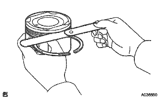
16. INSPECT PISTON RING GROOVE CLEARANCE
a. Using a feeler gauge, measure the clearance between the piston ring and the wall of the ring groove.
Ring groove clearance: 0.030 to 0.070 mm (0.0012 to 0.0028 inch)
If the clearance is not as specified, replace the piston.
17. INSPECT PISTON RING END GAP
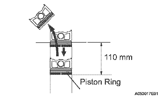
a. Using a piston, push the piston ring a little beyond the bottom of the ring travel, 110 mm (4.33 inch) from the top of the cylinder block.
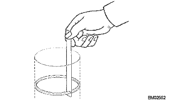
b. Using a feeler gauge, measure the end gap.
Specified End Gap:

If the end gap is greater than the maximum, replace the piston ring. If the end gap is greater than the maximum even with a new piston ring, replace the cylinder block.
18. INSPECT PISTON PIN OIL CLEARANCE
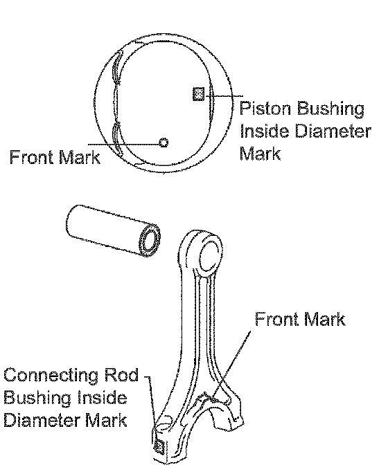
a. Inspect piston pin oil clearance.
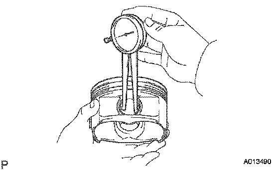
1 Using a caliper gauge, measure the pin hole diameter of the piston.
Pin hole diameter: 22.001 to 22.010 mm (0.8662 to 0.8665 inch)
Pin Hole Diameter (Reference):

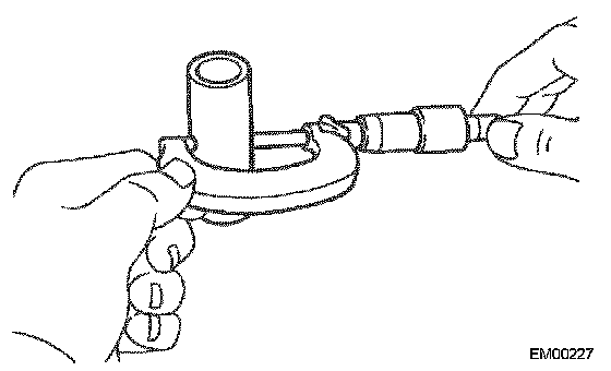
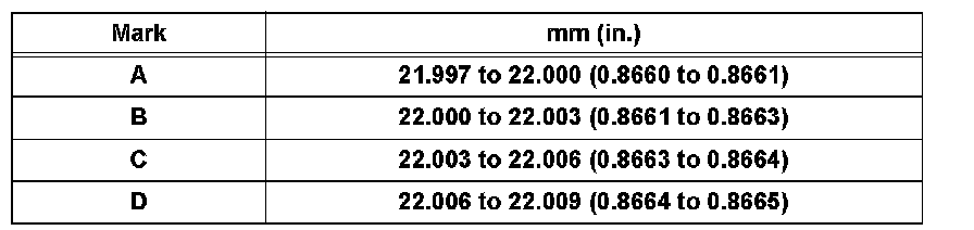
b. Using a micrometer, measure the piston pin diameter.
Piston pin diameter: 21.997 to 22.009 mm (0.8660 to 0.8665 inch)
Piston Pin Diameter (Reference):
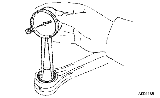
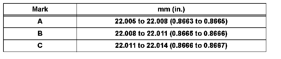
c. Using a caliper gauge, measure the inside diameter of the connecting rod bush.
Bushing inside diameter: 22.005 to 22.014 mm (0.8663 to 0.8667 inch)
Bushing Inside Diameter:
d. Subtract the piston pin diameter measurement from the piton pin hole diameter measurement.
Specified oil clearance: 0.001 to 0.010 mm (0.00004 to 0.00039 inch)
If the oil clearance is greater than the maximum, replace the connecting rod. If necessary, replace the piston and piston pin as a set.
e. Subtract the piston pin diameter measurement from the bushing inside diameter measurement.
Specified oil clearance: 0.005 to 0.100 mm (0.0002 to 0.0020 inch)
If the oil clearance is greater than the maximum, replace the connecting rod. If necessary, replace the connecting rod and piston pin as a set.
19. INSPECT CONNECTING ROD SUB-ASSEMBLY
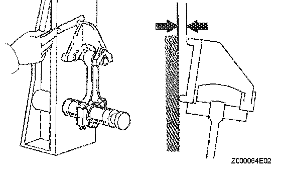
a. Using a rod aligner and feeler gauge, check the connecting rod alignment.
1 Check for alignment deviation.
Maximum alignment deviation: 0.05 mm (0.0020 inch) per 100 mm (3.94 inch)
If the alignment deviation is greater than the maximum, replace the connecting rod assembly.
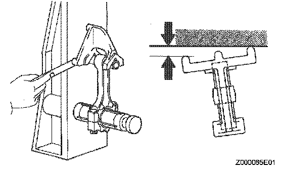
2 Check for twist.
Maximum twist: 0.15 mm (0.0059 inch) per 100 mm (3.94 inch)
If the twist is greater than the maximum, replace the connecting rod assembly.
20. INSPECT CONNECTING ROD BOLT
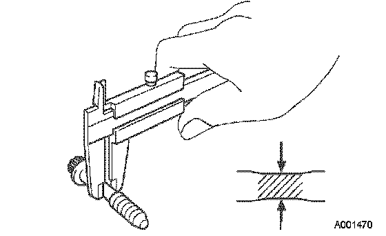
a. Using a vernier caliper, measure the tension portion diameter of the bolt.
Specified diameter: 7.0 to 7.3 mm (0.276 to 0.287 inch)
If the diameter is less than the minimum, replace the bolt.
21. INSPECT CRANKSHAFT
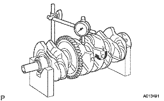
a. Using a dial indicator and V-blocks, measure the circle runout, as shown in the illustration.
Maximum circle runout: 0.03 mm (0.0012 inch)
If the circle runout is greater than the maximum, replace the crankshaft.
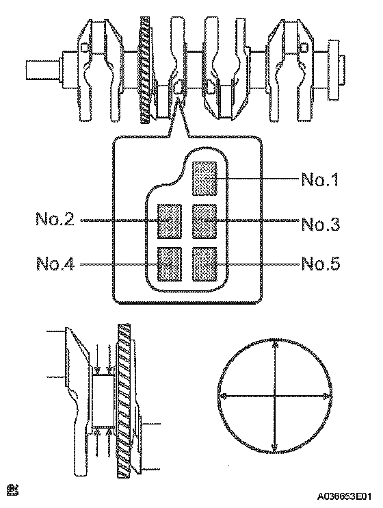
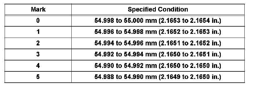
b. Using a micrometer, measure the diameter of each main journal.
Diameter: 54.988 to 55.000 (2.1648 to 2.06535 inch)
If the diameter is not as specified, check the oil clearance. If necessary, replace the crankshaft.
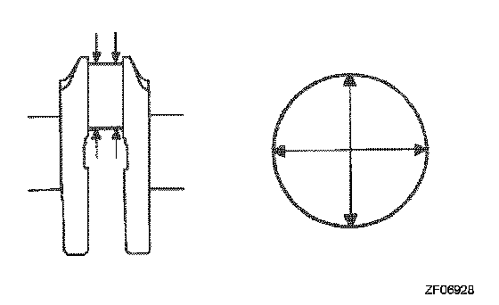
c. Check each main journal for taper and out-of-round as shown in the illustration.
Maximum taper and out-of-round: 0.003 mm (0.0001 inch)
If the taper and out-of-round is greater than the maximum, replace the crankshaft.
Diameter (Reference):
d. Using a micrometer, measure the diameter of each crank pin.
Diameter: 47.990 to 48.000 mm (1.8894 to 1.8898 inch)
If the diameter is not as specified, check the oil clearance. If necessary, replace the crankshaft.
e. Check each crank pin for taper and out-of-round as shown in the illustration.
Maximum taper and out-of-round: 0.003 mm (0.0001 inch)
If the taper and out-of-round is greater than the maximum, replace the crankshaft.
22. INSPECT CRANKSHAFT BEARING CAP SET BOLT
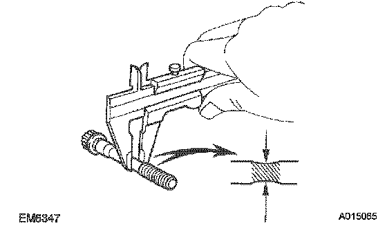
a. Using a vernier caliper, measure the tension portion diameter of the bolt.
Specified diameter: 7.2 to 7.6 mm (0.283 to 0.299 inch)
If the diameter is less than the minimum, replace the bolt.