Removal and Installation
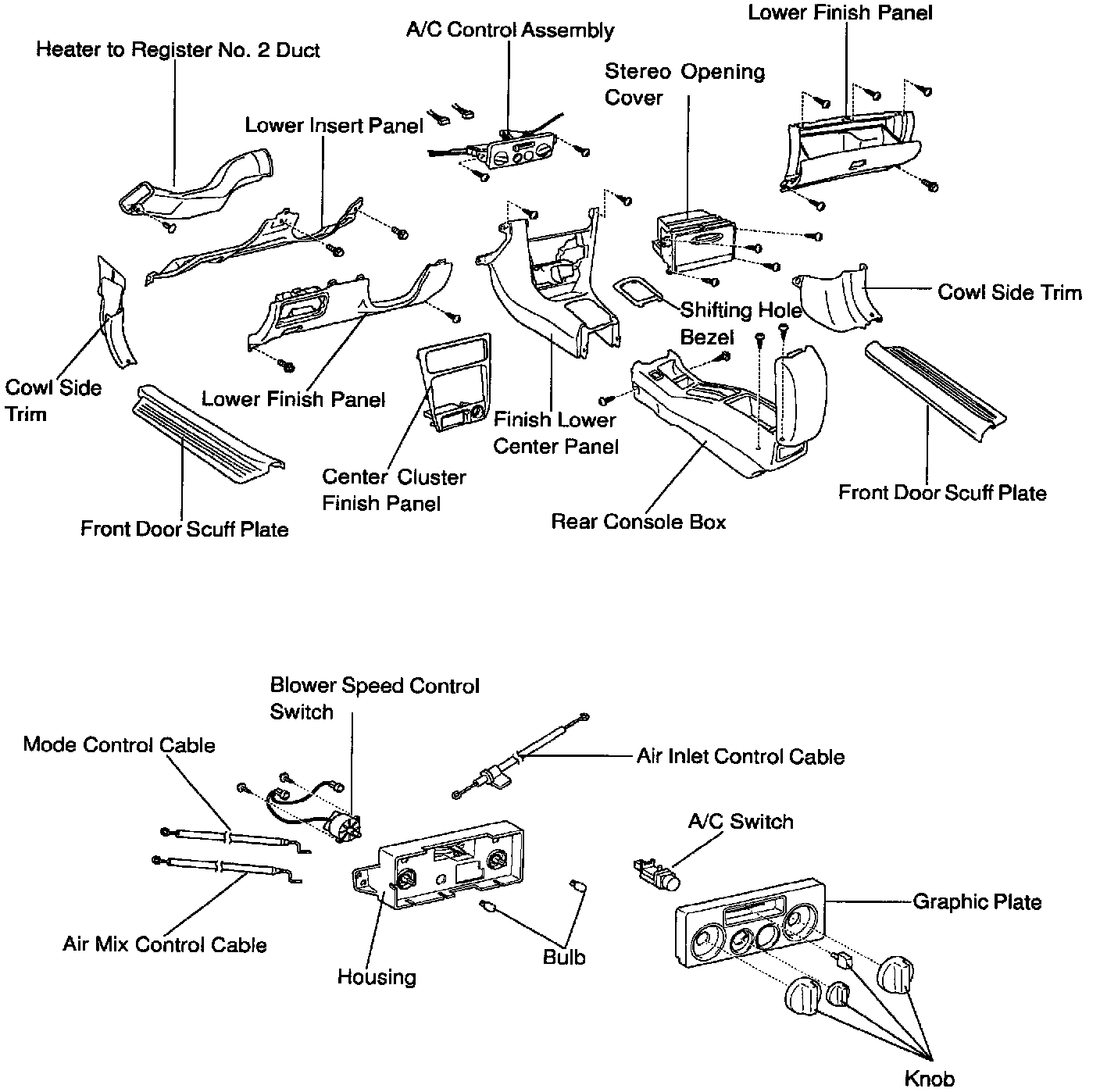
COMPONENTS
REMOVAL
1. REMOVE THESE PARTS:
a. Cowl side trims
b. Front door scuff plates
c. Lower finish panel
d. Lower insert panel
e. Center cluster finish panel
f. Heater to register No. 2 duct
g. Lower panel
h. Rear console box
i. Shifting hole bezel
j. Finish lower center panel
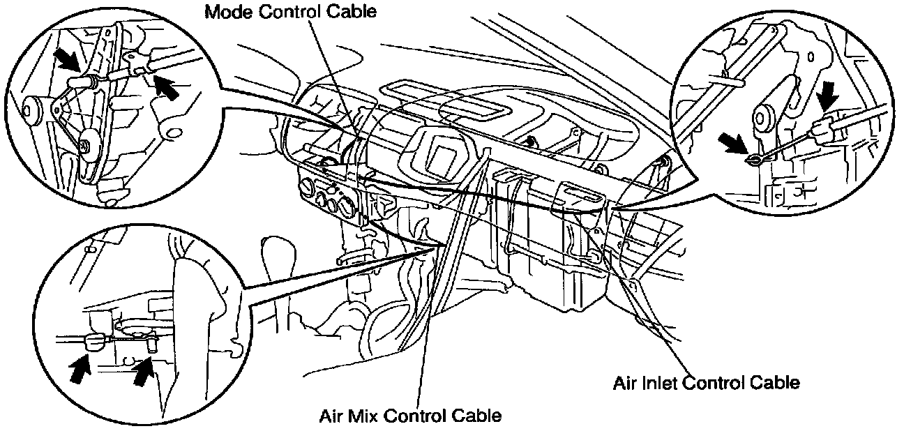
2. DISCONNECT HEATER CONTROL CABLE
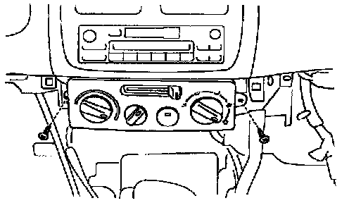
3. REMOVE A/C CONTROL ASSEMBLY
Remove the 2 screws and pull out the A/C control assembly, then disconnect the connector.
NOTE: Be careful not to vent the mode control cable, when pull out the A/C control assembly.
INSTALLATION
Installation is in the reverse order of Removal.
1. AFTER INSTALLATION, INSPECT HEATER CONTROL DIALS AND LEVER OPERATION
Move the control dials and lever left and right, check for stiffness and binding the full range of the lever and dials.
If there is stiffness or binding, proceed next step.
2. ADJUST HEATER CONTROL CABLES
a. Set A/C control assembly in these conditions.
1. Air inlet control lever at "RECIRC" position
2. Temperature control dial at "MAX COOL" position
3. Mode control dial at "DEF" position
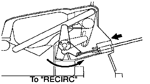
b. Adjust air inlet control cable.
1. Set air inlet damper control lever to "RECIRC" position.
2. Install inner cable to lever pin and clamp the outer cable.
HINT: Lock the clamp while lightly pushing the outer cable to the direction shown by arrow in the illustration.
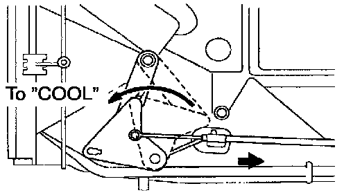
c. Adjust air mix control cable.
1. Set air mix damper control lever to "COOL" position.
2. Install inner cable to lever pin and clamp the outer cable.
HINT: Lock the clamp while lightly pulling the outer cable to the direction shown by arrow in the illustration.
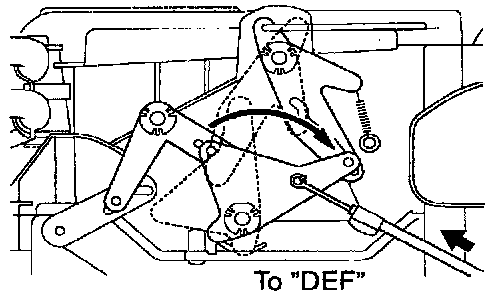
d. Adjust mode control cable.
1. Set mode control lever to "DEF" position
2. Install inner cable to lever pin and clamp the outer cable.
HINT: Lock the clamp while lightly pushing the outer cable to the direction shown by arrow in the illustration.