Compressor Clutch: Service and Repair
MAGNETIC CLUTCH DISASSEMBLYMagnetic Clutch:
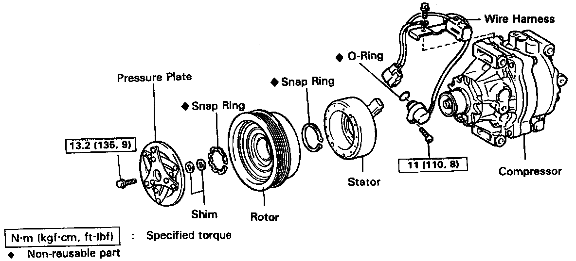
1. REMOVE PRESSURE PLATE
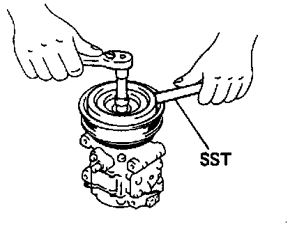
a. Using SST and a socket wrench. remove the shaft bolt.
SST 07112-76050
Torque: 13.2 N.m (135 kgf.cm. 9 ft.lbf)
b. Install SST to the pressure plate.
SST 07112-66040
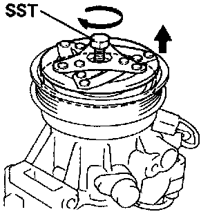
c. Using SST and a socket wrench. remove the pressure plate.
SST 07112-76050,07112-66040
d. Remove the shims from the shaft.
2. REMOVE ROTOR
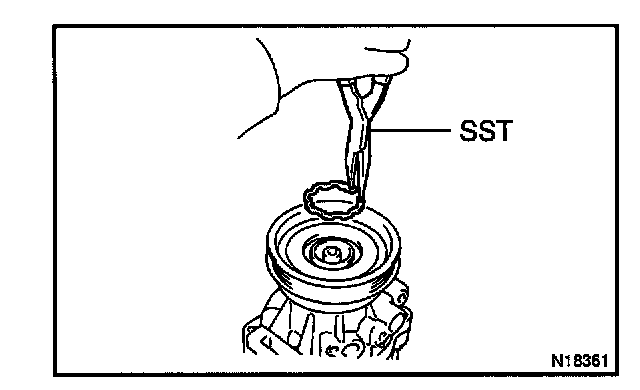
a. Using SST. remove the snap ring.
SST 07114-84020
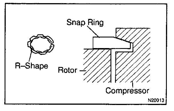
ASSEMBLY NOTE: The snap ring should be installed so that its beveled side faces up.
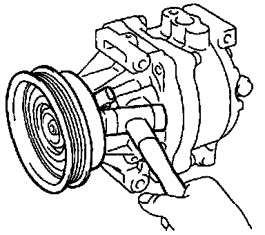
b. Using a plastic hammer. tap the rotor off the shaft.
DISASSEMBLY NOTE: Be careful not to damage the pulley when tapping on the rotor.
3. REMOVE STATOR
a. Disconnect the connector from the stator.
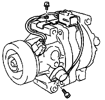
b. Using SST, remove the bolts from revolution detecting sensor.
SST 07110-61050
Torque: 11 N.m (110 kgf.cm, 8 ft.lbf)
c. Remove the screw and stator lead wire with the sensor.
ASSEMBLY HINT: Lubricate a new O-rings with compressor oil and install the sensor.
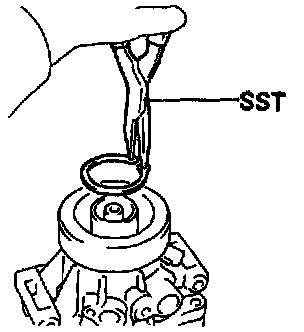
d. Using SST, remove the snap ring.
SST 07114-84020
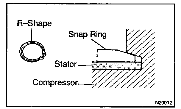
ASSEMBLY NOTE: The snap ring should be installed so that its beveled side faces up.
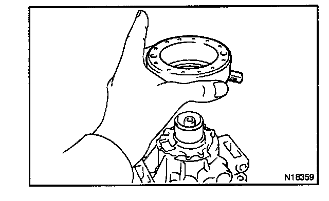
e. Remove the stator.
MAGNETIC CLUTCH ASSEMBLY
Assembly is in the reverse order to disassembly.
INSPECT CLEARANCE OF MAGNETIC CLUTCH
Clearance Check