Removal and Replacement
Control Valve BodyREMOVAL
1) Set the vehicle on a lift.
2) Disconnect the ground cable from the battery.
3) Lift up the vehicle.
4) Clean the transmission exterior.
5) Remove the drain plug (ATF) and gasket to drain ATF.
CAUTION: Immediately after the vehicle has been running, the ATF is very hot. Be careful not to burn yourself.
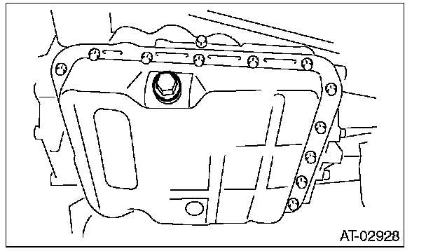
6) Replace the gasket with new part, and then tighten the drain plug (ATF).
Tightening torque: 25 N-m (2.5 kgf-m, 18.4 ft-lb)
7) Remove the oil pan.
CAUTION: Be careful not to allow foreign matter such as dust or dirt to enter the oil pan.
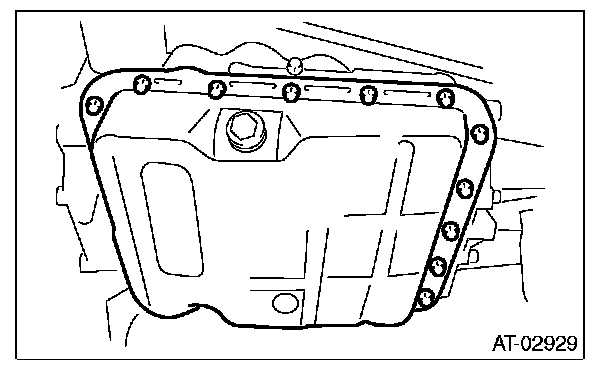
8) Remove the magnet.
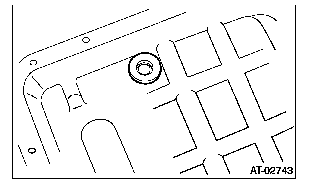
9) Clean the magnet.
10) Completely remove the remaining liquid gasket on the transmission case and oil pan.
11) Remove the control valve connector.
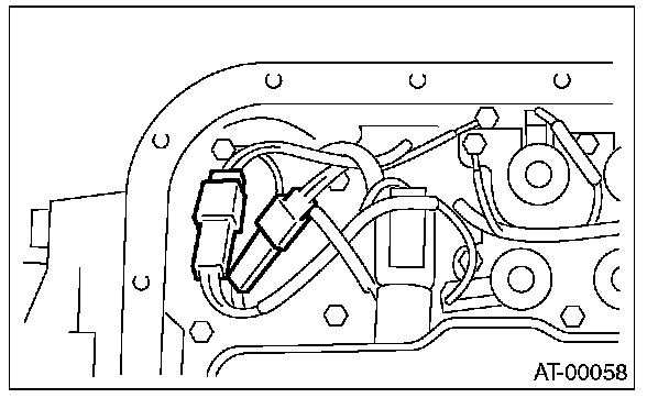
12) Remove the ATF cooler pipe.
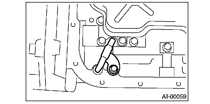
13) Remove the control valve body.
NOTE: The control valve body is replaced as an assembly only, because it is a non-disassembly part.
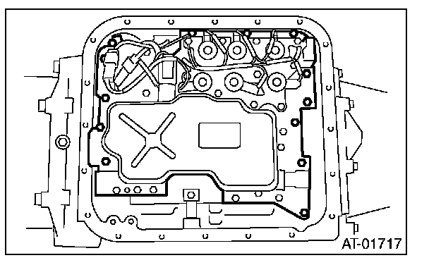
INSTALLATION
1) Check the control valve body for dust and other foreign matter.
2) Temporarily install the control valve body and ground cable to the transmission, then install the oil cooler pipe.
Tightening torque: 8 N-m (0.8 kgf-m, 5.8 ft-lb)
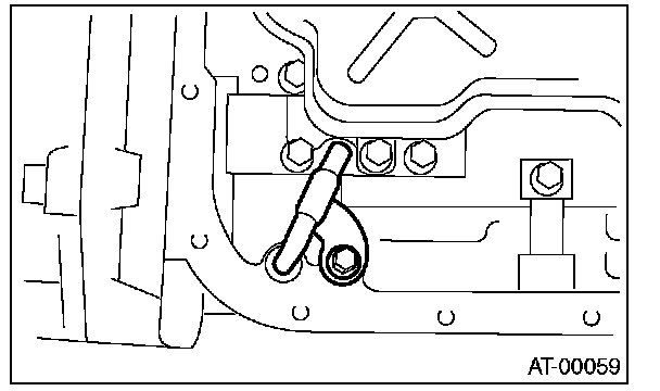
3) Tighten the bolts equally.
Tightening torque: 8 N-m (0.8 kgf-m, 5.8 ft-lb)
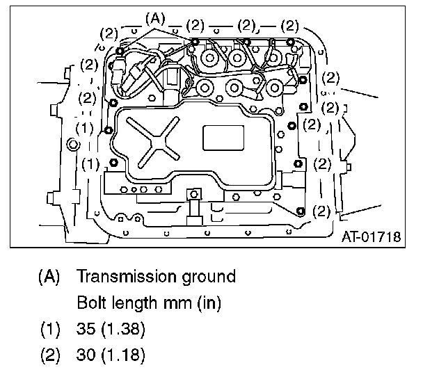
4) Connect the control valve connector.
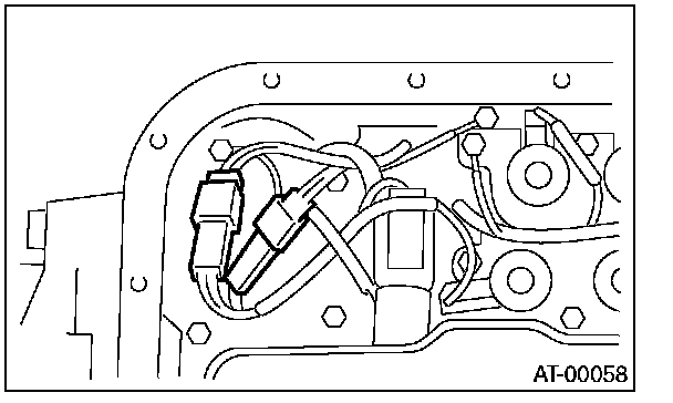
5) Attach the magnet at the specified position of the oil pan.
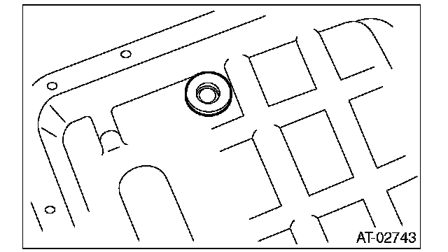
6) Apply proper amount of liquid gasket to the entire oil pan mating surface.
Liquid gasket: THREE BOND 1217B (Part No. K0877YA020) or equivalent
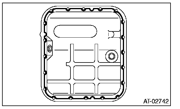
7) Fill the 3 holes aside from the bolt holes in the transmission case, with liquid gasket.
Liquid gasket: THREE BOND 1217B (Part No. K0877YA020) or equivalent
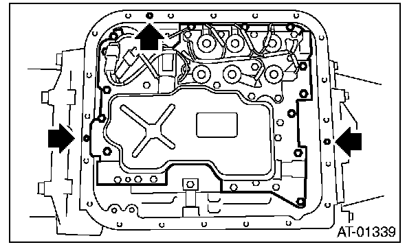
8) Install the oil pan by equally tightening the bolts.
Tightening torque: 5 N-m (0.5 kgf-m, 3.7 ft-lb)
9) Fill ATF from the oil charge pipe.
Recommended fluid: SUBARU ATF HP
Substitute fluid: IDEMITSU: ATF HP
CASTROL: TRANSMAX J
Capacity: Fill with the same amount of fluid that was drained from the drain plug hole.
10) Bleed out air from the control valve body.
11) Check the ATF level.
12) Execute the learning control promotion.
INSPECTION
Make sure there are no holes, bending damage or other foreign materials on each parts.
Air Bleeding of Control Valve
NOTE
When ATF is drained from the automatic transmission, make sure to bleed air from the control valve after filling with the specified amount of ATF.
PROCEDURE
1) Shift the select lever to "P" range, and apply the parking brake.
2) Lift up the vehicle.
NOTE: When air bleeding the control valve, the lower part of the tire is to be lifted more than 30 cm above the ground.
3) Connect the Subaru Select Monitor to the data link connector, and then turn the ignition switch to ON (Engine OFF).
4) Perform {Clear Memory} using the Subaru Select Monitor.
5) Using the Subaru Select Monitor, check that there is no DTC displayed.
6) Check that the ATF temperature displayed on the Subaru Select Monitor is 60°C (140°F) or less. 7) Shift the select lever to "R" range.
8) Turn the ignition key to OFF.
9) When "communication error occurred." is displayed on Subaru Select Monitor, select "OK", and when "Store the data before communication error occurred?" appears, select "NO" and exit the Subaru Select Monitor.
10) Fully depress the brake pedal until the control valve air bleeding work is completed.
11) Turn the ignition switch to ON (engine OFF).
12) Shift the select lever to the "P" range, and wait for 3 seconds or more.
13) Shift the select lever to the "R" range, and wait for 3 seconds or more.
14) Shift the select lever to the "N" range, and wait for 3 seconds or more.
15) Shift the select lever to the "D" range, and wait for 3 seconds or more.
16) Shift the select lever to the "N" range, and wait for 3 seconds or more.
17) Slowly depress the accelerator pedal to full throttle.
18) Slowly release the accelerator pedal completely.
19) Start the engine, and idle it.
20) Shift the select lever to "D" range.
21) Set the Subaru Select Monitor to "READ CURRENT DATA".
22) Start the control valve air bleed operation. At this time, the AT oil temperature warning light in the combination meter start blinking at 2 Hz. When the AT oil temperature warning light does not blink, turn the ignition switch to OFF and repeat the procedures from step 4). When the AT oil temperature warning light that was flashing at 2 Hz turns off, the control valve air bleed operation is complete.
NOTE: If the AT oil temperature warning light changes from blinking at 2 Hz to 4 Hz during the control valve air bleed, repeat the procedure from step 4).
23) Shift the select lever to "N" range, and then turn the ignition switch to OFF.
24) Shift the select lever to "P" range.