Overhaul
DISASSEMBLYAT MODEL
1) Remove the brake switch.
2) Unbolt, and then remove the brake pedal.
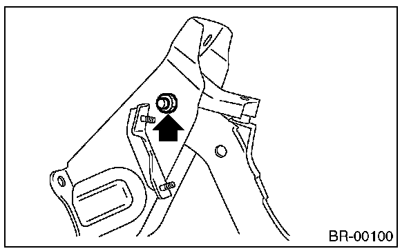
3) Remove the bushing, stopper and spring.
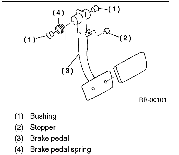
4) Remove the brake pedal pad.
MT MODEL
1) Remove the brake switch.
2) Remove the clutch pedal.
3) Remove the clutch master cylinder bracket.
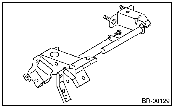
4) Remove the bushing, spring and stopper.
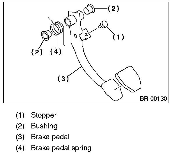
5) Remove the brake pedal pad.
ASSEMBLY
1) Position the stop light switch, etc. to the brake pedal.
2) Clean the inside of bores of the clutch pedal and brake pedal, apply grease, and set bushings into the bores.
3) Align bores of the pedal bracket, clutch pedal and brake pedal, attach brake pedal return spring and clutch pedal effort reduction spring (vehicles equipped with hill holder), then install the pedal bolt.
NOTE: Clean up the inside of bushings and apply a thin coat of grease before installing the spacer.
Tightening torque: T: 29 N-m (3.0 kgf-m, 21.4 ft-lb)
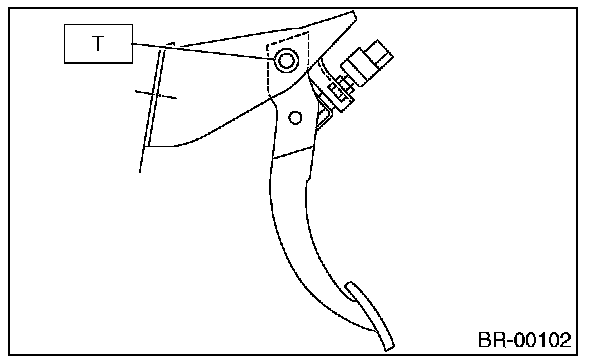
4) After attaching the brake pedal to the vehicle, adjust the position of the stop light switch.
INSPECTION
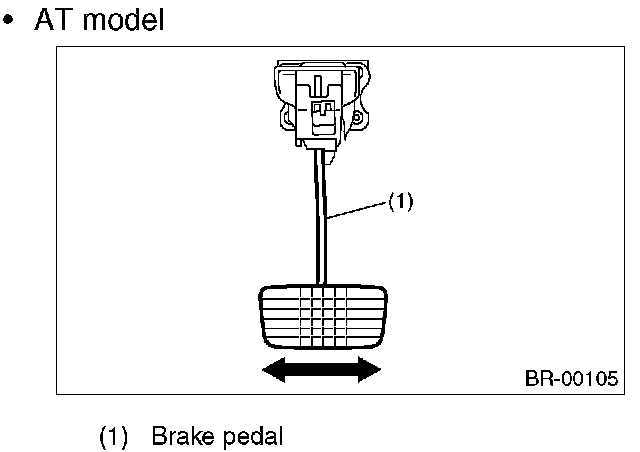
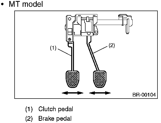
1) Move the brake and clutch pedal pads in the lateral direction with a force of approx. 10 N (1 kgf, 2 lb), and check the pedal deflection is in the range of specifications.
CAUTION: If excessive deflection is found, replace the bushing with new part.
Deflection of the brake and clutch pedal
Service limit: 5.0 mm (0. 197 in) or less
^ AT model
^ MT model
2) Check the position of pedal pad. pedal height.
"L" 148 mm (5.83 in)
Brake pedal free play. A 1 - 3 mm (0.04 - 0.12 in) [Depress brake pedal with a force of less than 10 N (1 kgf, 2 lb).]]
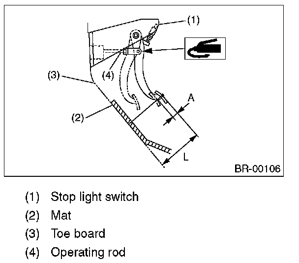
3) If it is not within the specification, adjust it by adjusting the brake booster operating rod length.