Engine Carrier
Removing and installing engine carrier
Preliminary work
Danger
Vehicle can fall down
^ Risk of squashing or crushing
^ Risk of damage to the vehicle
-> Do not place any solid objects under the raised vehicle.
-> Ensure that the lifting platform is prevented from lowering.
-> Remove solid objects before lowering the vehicle.
-> Raise the vehicle only at the take-up points provided.
1. Remove rear wall cover in the passenger compartment.
2. Remove rear and center underbody panelling.
Removing engine carrier
Danger
Risk of engine falling down.
^ Danger of fatal injury, material damage.
-> Support the engine with the prescribed tool.
Information
Specifications for wrench sizes (a/f specifications) for screw heads are described as follows:
^ Torx screws: (E..) for external Torx, (T..) for internal Torx.
^ Hexagon-head bolts (internal and external hexagon): Wrench size (a/f)
1. Unscrew one M10 x 35 hexagon-head bolt (a/f 16) -2- on the engine bracket through the maintenance opening in the passenger compartment.
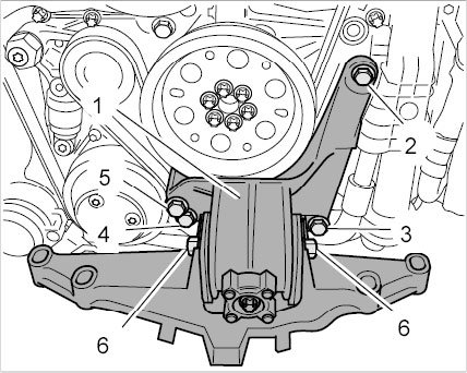
Engine carrier (shown on removed engine)
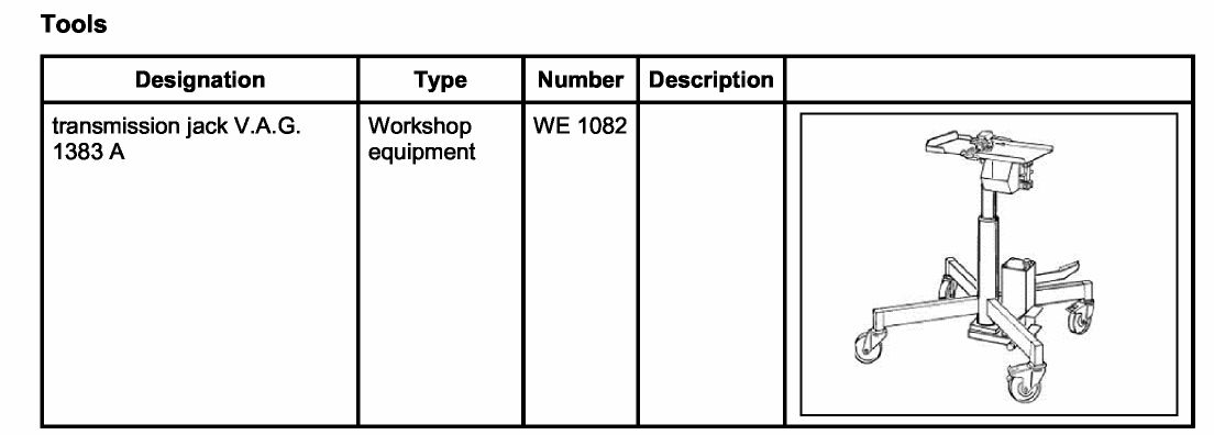
2. Support the engine using transmission jack V.A.G. 1383 A WE 1082 and transmission jack plate on the oil pan.
2.1. The weight must be distributed uniformly on the oil pan, not just in one specific area.
3. Loosen screws on lower part of engine carrier -1-.
3.1. Remove holder for coolant pipes -5- on the underbody. Unscrew two M6 hexagon nuts -4- and remove the holder.
3.2. Leave coolant pipes hanging freely.
3.3. Unscrew four M10 collar nuts (a/f 16) -2- on the lower part of the engine carrier.
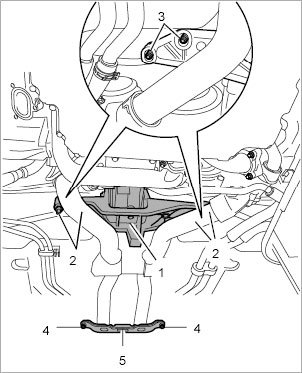
Engine carrier and holder for coolant pipes
4. Slowly lower the engine by about 30 mm using transmission jack V.A.G. 1383 A WE 1082.
5. Remove engine carrier bracket -1-.
5.1. Unscrew M10 collar nuts (a/f 18) -6- on the engine mounting, pull out M10 x 115 hexagon-head bolt (a/f 18) -6- and remove lower part of engine carrier.
5.2. Unscrew three M10 hexagon-head bolts (a/f 16) -3 to 5-.
5.3. Remove engine carrier bracket downwards.
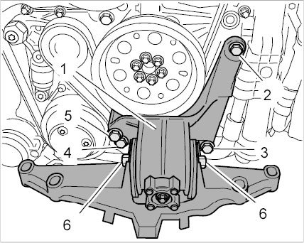
Engine carrier (shown on removed engine)
1 - Engine carrier
2 - Hexagon-head bolt, M10 x 35
3 - Hexagon-head bolt, M10 x 65
4 - Hexagon-head bolt, M10 x 115
5 - Hexagon-head bolt, M10 x 135
6 - Hexagon-head bolt, M10 x 115 and M10 collar nut on engine mounting
6. Check engine carrier -1- and engine mounting for damage (cracks, deformation, vulcanization cracks) and replace them if necessary.
7. Clean contact surfaces.
Installing engine carrier
Information
Specifications for wrench sizes (a/f specifications) for screw heads are described as follows:
^ Torx screws: (E..) for external Torx, (T..) for internal Torx.
^ Hexagon-head bolts (internal and external hexagon): Wrench size (a/f)
Danger
Risk of engine falling down.
^ Danger of fatal injury, material damage.
-> Support the engine with the prescribed tool.
1. Check that the engine is supported correctly.
2. Install engine carrier bracket -1-.
2.1. Position the bracket on the engine.
2.2. Screw in three hexagon-head bolts (a/f 16) -3 to 5-.
2.3. Fit one M10 x 35 hexagon-head bolt (a/f 16) -2- through the maintenance opening in the passenger compartment.
2.4. Fit hexagon-head bolts (a/f 16) -2 to 5- uniformly and tighten to the prescribed torque.
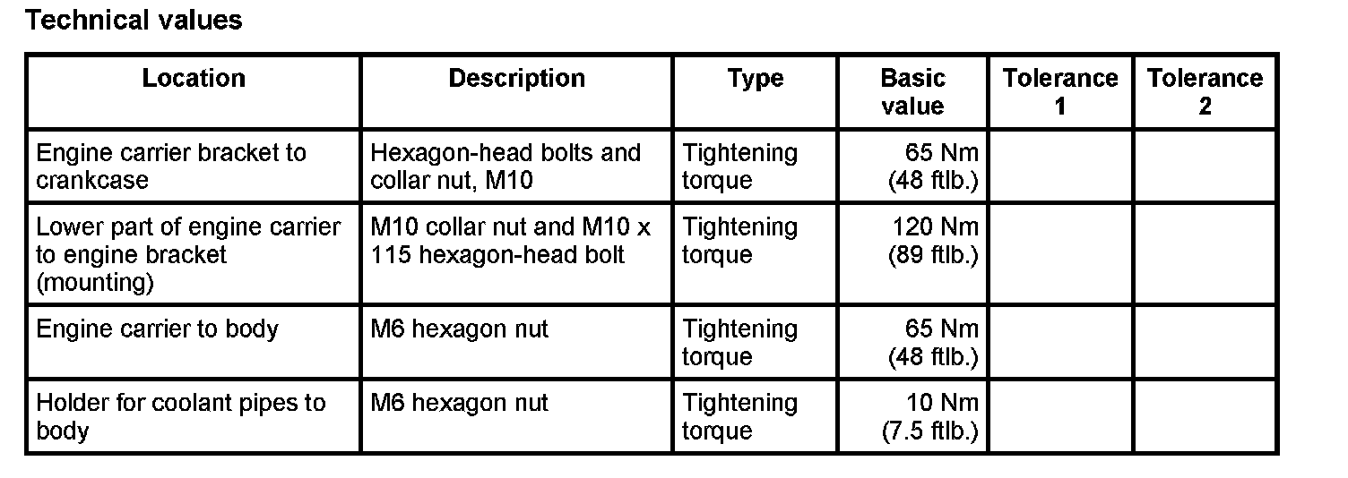
-> Tightening torque: 65 Nm (48 ftlb.)
1 - Engine carrier
2 - Hexagon-head bolt, M10 x 35
3 - Hexagon-head bolt, M10 x 65
4 - Hexagon-head bolt, M10 x 115
5 - Hexagon-head bolt, M10 x 135
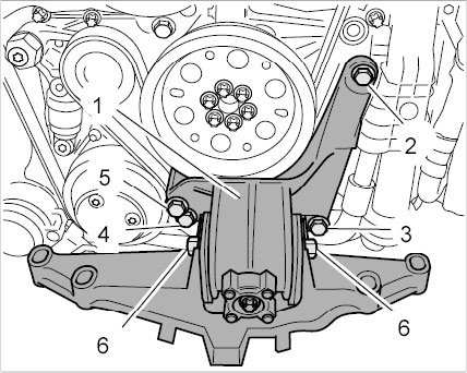
Engine carrier
6 - Hexagon-head bolt, M10 x 115 and M10 collar nut on engine mounting
3. Install lower part of engine carrier. Observe direction of travel arrow -1- on the component.
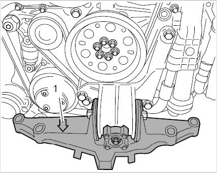
Direction of travel arrow on engine carrier
3.1. Fit lower part on the engine mounting. Slide hexagon-head bolt (M10 x 115, a/f 18) through from the right (in direction of travel) and fit M10 collar nut (a/f 18).
3.2. As a positioning aid, slide a long M10 screw or a mandrel with a diameter of 10 mm through at the through-hole -arrow- in the lower part of the engine carrier.
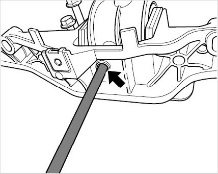
Positioning aid for lower part of engine carrier
Insert the mandrel or screw into the bore on the engine mounting -arrow-.
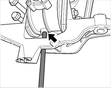
Securing engine mounting to lower part of engine carrier
3.3. Tighten the collar nut on the engine mounting and counter at the hexagon-head bolt. Get a second person to hold the positioning aid securely.
-> Tightening torque: 120 Nm (89 ftlb.)
3.4. Lift up the engine using transmission jack V.A.G. 1383 A WE 1082 until the lower part of the engine carrier is touching the body.
3.5. Screw four M10 collar nuts -2- onto the threaded bolts -3-.
3.6. Tighten collar nuts to the specified torque.
-> Tightening torque: 65 Nm (48 ftlb.)
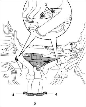
Engine carrier and holder for coolant pipes
4. Fit holder for coolant pipes -5- using two M6 hexagon nuts -4-.
-> Tightening torque: 10 Nm (7.5 ftlb.)
5. Remove transmission jack from the work area.
Subsequent work
Danger
Vehicle can fall down
^ Risk of squashing or crushing
^ Risk of damage to the vehicle
-> Do not place any solid objects under the raised vehicle.
-> Ensure that the lifting platform is prevented from lowering.
-> Remove solid objects before lowering the vehicle.
-> Raise the vehicle only at the take-up points provided.
1. Fit rear and center underbody panelling.
2. Install rear wall cover in the passenger compartment.