Brake Rotor Replacement
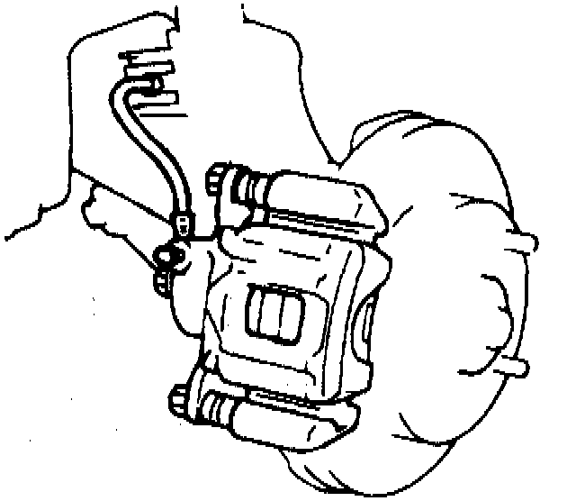
REMOVAL PROCEDURE
^ TOOLS REQUIRED
- J26900-1 Outside Micrometer
1. Siphon two-thirds of the fluid from the master cylinder reservoir.
2. Raise the vehicle. Support the vehicle. Refer the Vehicle Lifting and Jacking in General Information.
3. Remove the tire and wheel assembly.
4. Remove the two caliper carrier bolts.
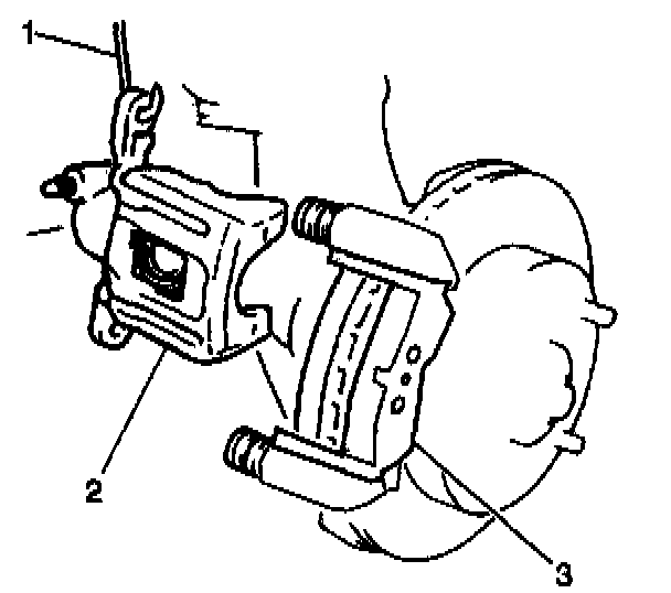
5. Lift the caliper carrier, along with the caliper (2) and pads (3). Suspend the caliper with a wire (1) in order to prevent damage to the brake hose.
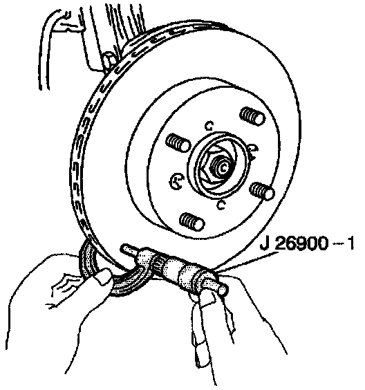
6. Use a J 26900-1 in order to measure the rotor thickness. If the rotor thickness is less than 15 mm (0.59 in), replace the rotor.
7. Remove two rotor screws.
8. Remove the rotor from the wheel hub. If the rotor cannot be removed by hand, install two 8 mm bolts into the rotor. Tightening the bolts will force the rotor off the wheel hub.
INSTALLATION PROCEDURE
1. Install the rotor to the wheel hub. Secure with two screws.
NOTICE: Refer to Service Precautions.
2. Install the caliper carrier, with the caliper and pads, into position. Secure with two caliper carrier bolts.
^ Tighten the caliper carrier bolts to 40-60 Nm (29-43 ft. lbs.) .
3. Install the tire and wheel assembly.
4. Lower the vehicle.
5. Fill the master cylinder fluid reservoir.