Electronic Level Control Air Bladder - Replacement
Number 87-3-12 Date 3/87
REAR STRUT ELECTRONIC LEVEL CONTROL
Subject: AIR BLADDER REPLACEMENT
1987 BONNEVILLE MODELS WITH ELECTRONIC LEVEL CONTROL
Rear strut Electronic Level Control Air Bladder Service Kits are now available from GMSPO using Part Number 22062506. All struts which leak air at the ELC Bladder should be serviced using this kit rather than replacing complete strut assemblies.
TOOL REQUIRED:
J-34649 Sealing Ring Compressor
Figure 1 - Scribing Mount and Tube for Reassembly:
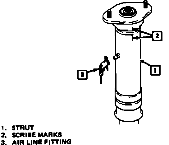
REMOVE OR DISCONNECT:
1. Strut from car.
2. Scribe upper mount and outer tube for reference on assembly. See Figure 1.
3. Mount strut in vise using hardwood blocks for additional clamping pressure.
Figure 2 - Removing Upper Mount from Strut:
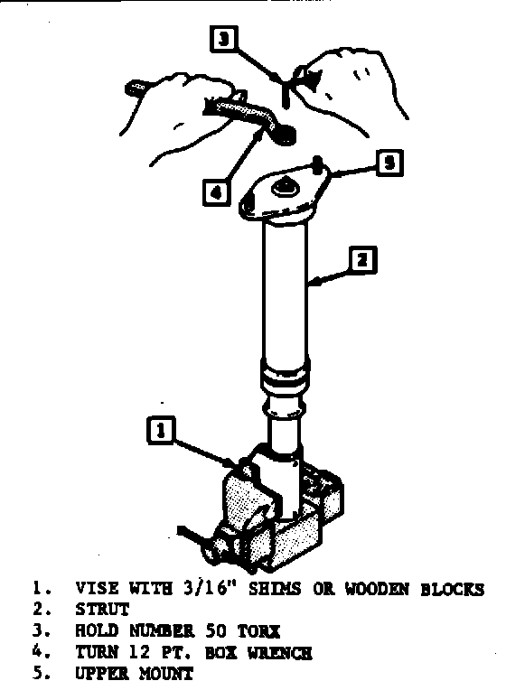
4.. Upper mount from strut, Figure 2.
Figure 3 - Removing Outer Clamp:
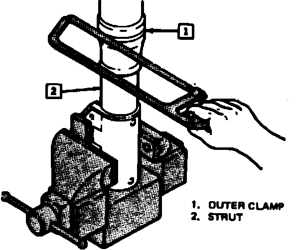
5. Outer clamp with hacksaw, Figure 3.
6. Cut air bladder from outer tube and slide inner tube up.
Figure 4 - Removing O-Ring:
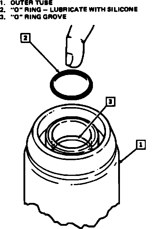
7. O-ring seal from inside top of outer tube, Figure 4.
Figure 5 - Removing Inner Clamp:
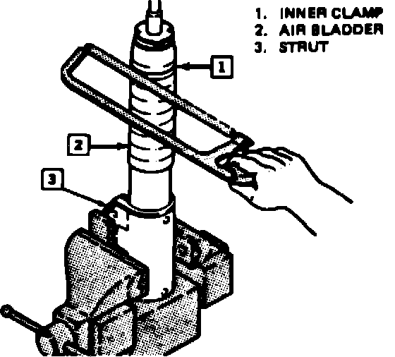
8. Inner clamp with hacksaw, Figure 5.
9. Air bladder from inner tube.
INSTALL OR CONNECT
Figure 4 - Removing O-Ring:
1. Lubricate new O-ring and O-ring groove with silicone lubricant and install new O-ring in groove, Figure 4.
Figure 6 - Lubricating New Air Bladder:
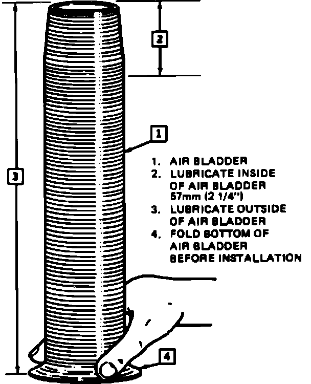
2. Silicone lubricant to inside top of new air bladder and entire outside of air bladder, Figure 6.
3. Fold bottom of air bladder before installing on inner tube.
Figure 7 - Installing Inner Clamp:
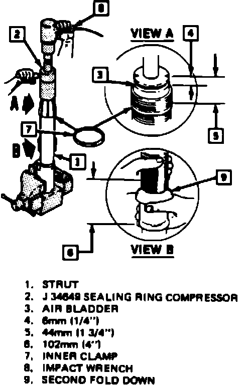
4. Air bladder over inner tube, continue folding bottom up. Position top of air bladder as indicated in Figure 7.
IMPORTANT: DO NOT USE TOOLS TO FOLD THE AIR BLADDER. USE OF TOOLS CAN CAUSE DAMAGE TO THE AIR BLADDER, RESULTING IN LEAKS.
Figure 7 - Installing Inner Clamp:
5. Inner clamp to top of air bladder at specified dimension, Figure 7.
6. Tighten inner clamp with J-34649.
7. Fold bottom of air bladder up and fold top of 102 mm (4") section down.
8. Apply silicone lubricant to polished diameter of inner tube shaft.
9. Outer tube over air bladder and push down against folded portion of air bladder.
IMPORTANT: OUTER TUBE MUST BE COMPLETELY SEATED OVER SHAFT.
10. Upper mount to strut and position as indicated. Tighten nut to 100 N-m (74 ft.lb.).
Figure 8 - Orientating Air Fitting:
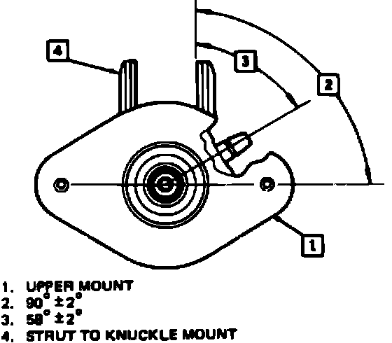
IMPORTANT: LINE UP SCRIBE MARKS ON UPPER MOUNT AND OUTER TUBE ON REASSEMBLY. UPPER MOUNT AND TUBE AIR FITTING MUST BE PROPERLY ORIENTED WITH RESPECT TO BOTTOM STRUT MOUNT, FIGURE 8.
Figure 9 - Lubricating Outer Tube:
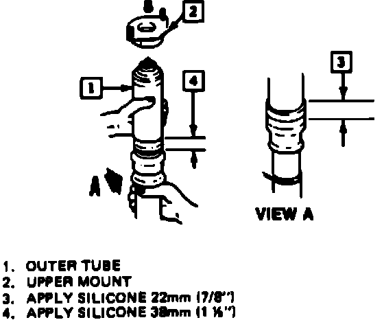
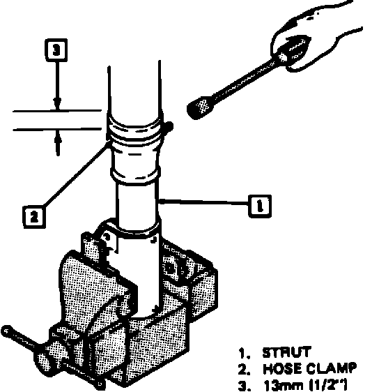
Figure 10 - Tightening Hose Clamps:
11. Silicone lubricant to outer tube, Figure 9.
12. Air bladder over bottom of outer tube by folding up over tube and continue pushing over tube.
13. Hose clamp over grooved area of air bladder and tighten.
14. Inspect for leaks with soap solution by supporting strut and connecting system air line to pressurize strut.
15. Strut to car.
WARRANTY INFORMATION:
For warranty purposes, use one of the following:
E5750 Rear Strut - Right Side
E5751 Rear Strut - Left Side
E5757 Rear Strut - Both Sides
Add .6 hours (each side) to replace Electronic Level Control Bladder.