Intake Manifold Replacement
Intake Manifold ReplacementRemoval Procedure
1. Disconnect the battery ground (negative) cable.
2. Remove the throttle body air inlet duct from the throttle body.
3. Partially drain the engine coolant from the cooling system.
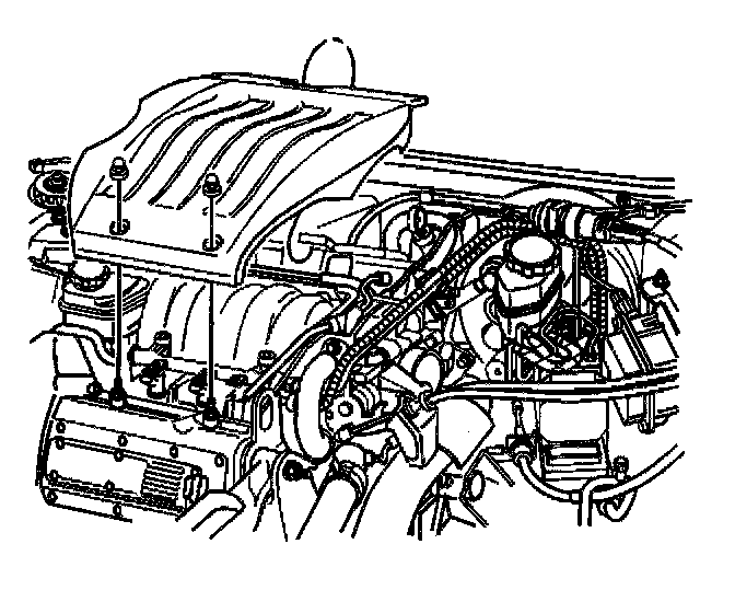
4. Remove the fuel injector sight shield.
5. Disconnect the throttle and cruise cables with the mounting bracket from the throttle body. Refer to the following procedures:
^ Accelerator Controls Cable Replacement
^ Accelerator Controls Cable Bracket Replacement
6. Remove the throttle body coolant hoses from the throttle body.
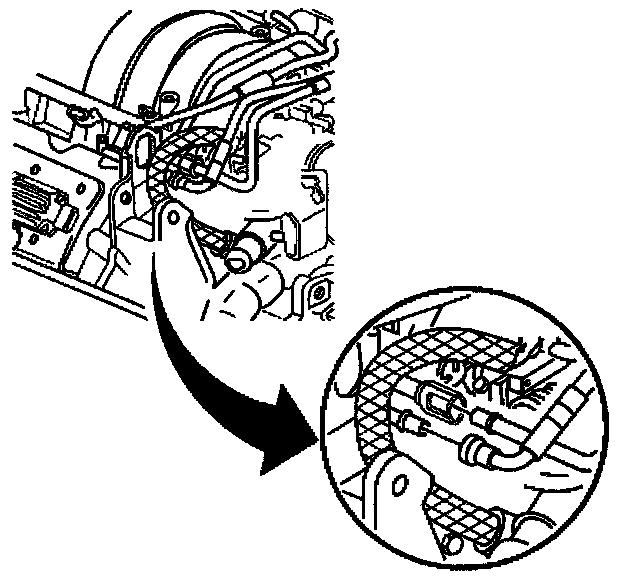
7. Disconnect the fuel lines from the fuel rail.
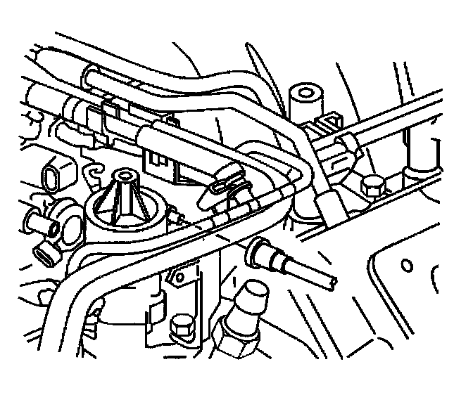
8. Disconnect the fuel vapor line from the EVAP canister purge solenoid.
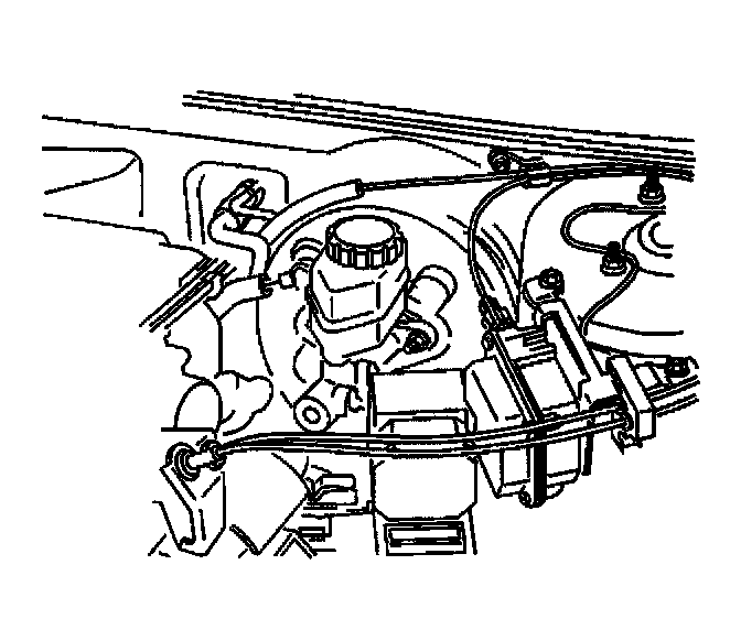
9. Remove the brake booster vacuum hose from the brake booster.
10. Remove the A/C vacuum hose from the intake manifold.
11. Remove the surge tank inlet pipe retainer from the fuel injector rail.
12. Disconnect the engine wiring harness connectors from the following components:
^ Fuel injectors
^ Throttle Position (TP) sensor
^ Idle Air Control (IAC) valve
^ EVAP canister purge solenoid
^ Manifold Absolute Pressure (MAP) sensor
13. Remove the engine wiring harness channel bolts from the camshaft covers.
14. Remove and set aside the engine wiring harness and channel.
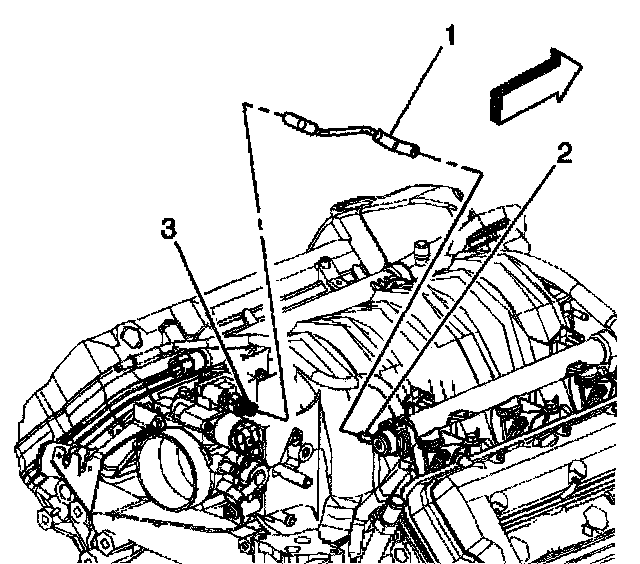
15. Remove the fuel pressure regulator vacuum tube (1) from the regulator (2) and the throttle body (3).
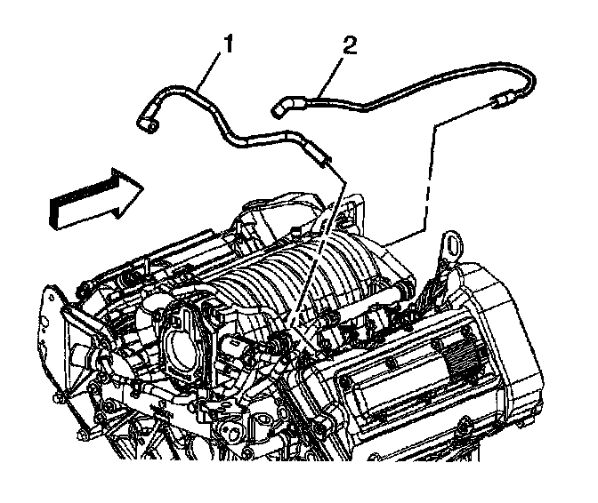
16. Disconnect and remove the PCV valve and both feed tubes (1, 2) from the camshaft covers and intake manifold.
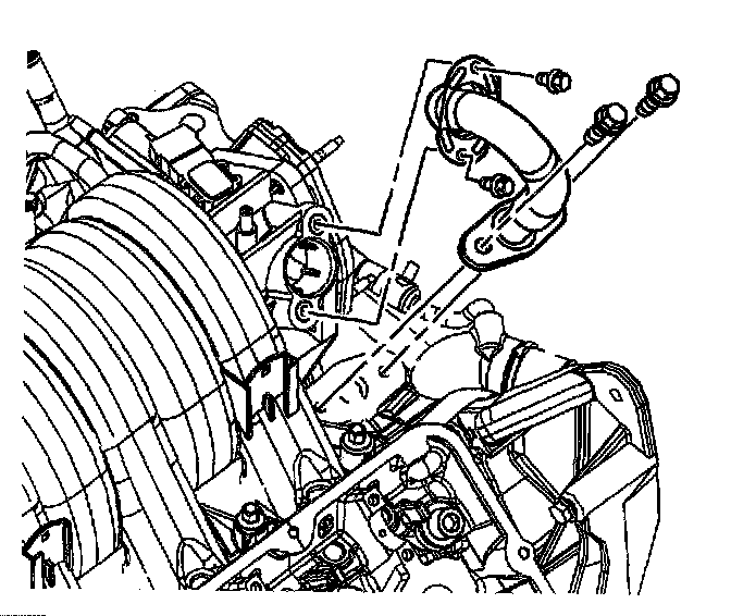
17. Remove the EGR valve outlet pipe retaining bolts from the intake manifold and the water crossover.
18. Remove the EGR valve outlet pipe.
19. Disconnect the 4 fuel rail snap-lock retainers by pushing toward the camshaft covers and lifting.
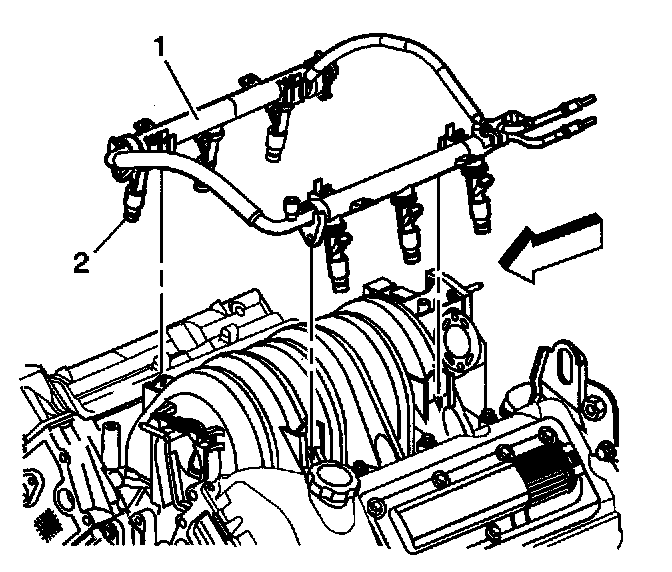
20. Remove the fuel rail (1) and fuel injectors (2) as an assembly and store in a clean, secure location away from any heat sources.
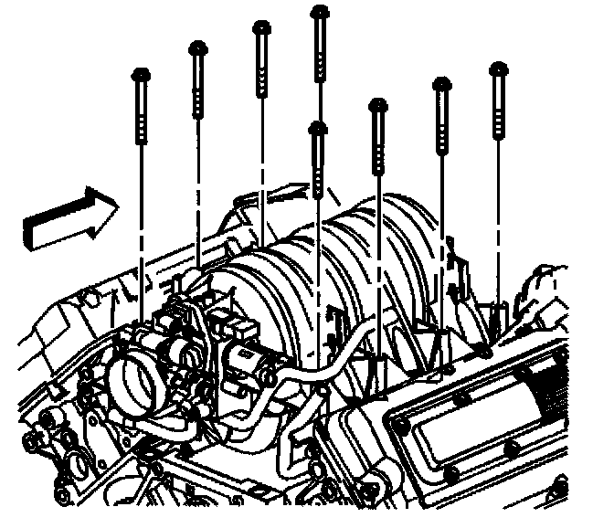
21. Remove the intake manifold bolts.
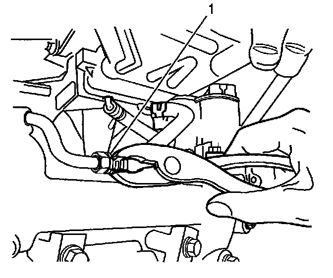
22. Remove the throttle body coolant hose from the water crossover feed tube (1).
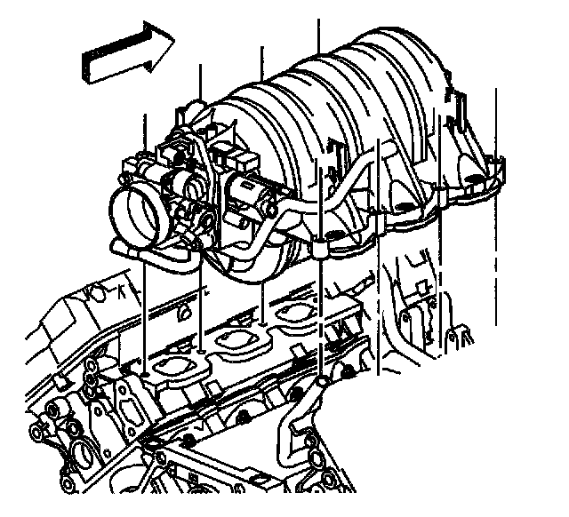
23. Remove the intake manifold.
Important: If you are replacing the intake manifold perform the following steps.
24. Disassemble the intake manifold.
25. Clean and inspect the intake manifold.
26. Assemble the intake manifold.
Installation Procedure
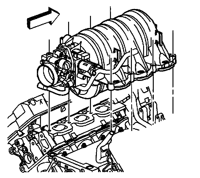
1. Install the intake manifold.
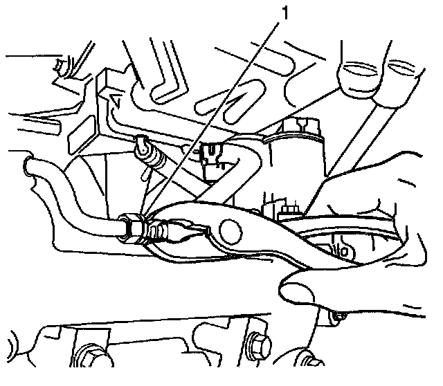
2. Install the throttle body heater hose to the water crossover feed tube (1).
3. Install the hose clamp.
Notice: Refer to Fastener Notice in Service Precautions.
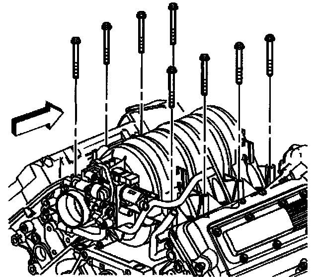
4. Install the intake manifold bolts.
Important: Tighten the intake manifold bolts in circular pattern starting from the center and moving outward.
Tighten the intake manifold bolts to 7 Nm (62 inch lbs.).
5. Inspect the fuel injector O-rings (2) for misalignment or damage. Replace the O-rings if necessary.
Important: Do not apply excessive pressure to the fuel rail when installing. If excessive pressure is needed to install the fuel rail then misalignment of a fuel injector could be the concern and using excessive pressure will only cause damage to the seal or intake manifold.
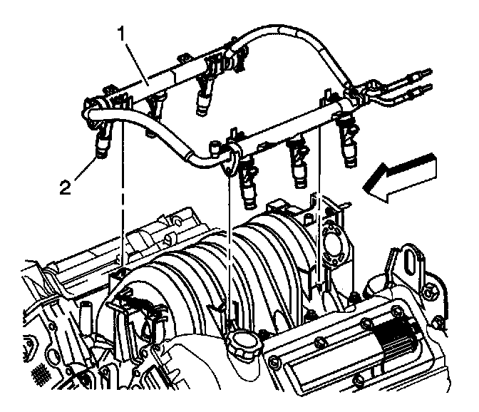
6. Install the fuel rail (1) and fuel injectors (2) by aligning the fuel injectors with their respective ports and pressing the four fuel rail snap-lock connectors into the intake manifold until they lock in place.
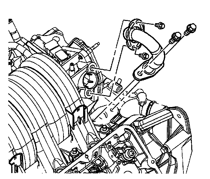
7. Install the EGR outlet pipe.
8. Install the EGR outlet pipe to intake manifold bolt.
Tighten the EGR outlet pipe to intake manifold bolt to 10 Nm (89 inch lbs.).
9. Install the EGR outlet pipe to water crossover bolt.
Tighten the EGR outlet pipe to water crossover bolt to 24 Nm (18 ft. lbs.).
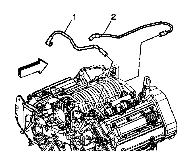
10. Install the PCV valve and connect both feed tubes (1, 2) to the camshaft covers and intake manifold.
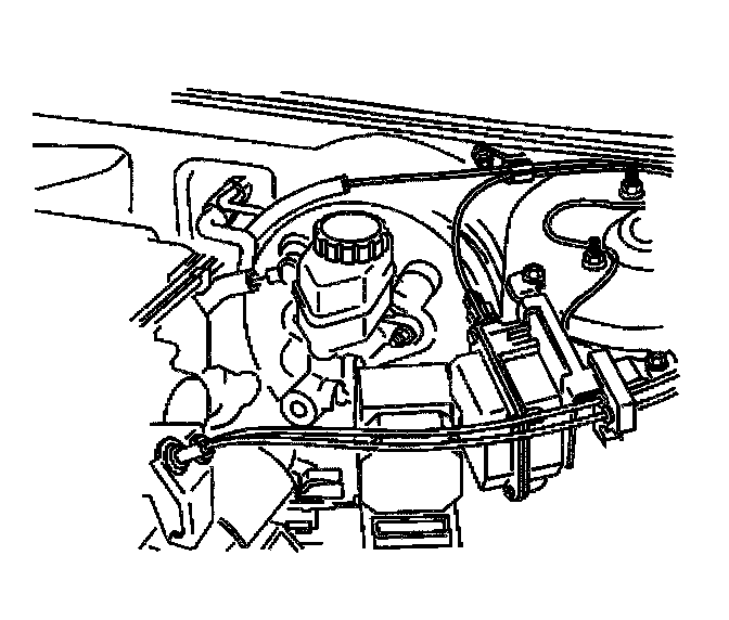
11. Install the brake booster vacuum hose to the brake booster.
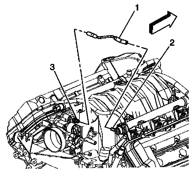
12. Install the fuel pressure regulator vacuum tube (1) to the regulator (2) and the throttle body (3).
13. Install the A/C vacuum hose to the intake manifold.
14. Install the engine wiring harness and channel.
15. Install the engine wiring harness channel bolts to the camshaft covers.
Tighten the engine wiring harness channel bolts to 10 Nm (89 inch lbs.).
16. Connect the surge tank inlet pipe retainer to the fuel injector rail.
17. Connect the engine wiring harness connectors to the following components:
^ Throttle Position (TP) sensor
^ Idle Air Control (IAC) valve
^ EVAP canister purge solenoid
^ Manifold Absolute Pressure (MAP) sensor
^ Fuel injectors
18. Connect the throttle body coolant hoses to the throttle body.
19. Connect the throttle and cruise control cables with the mounting bracket to the throttle body. Refer to the following procedures:
^ Accelerator Controls Cable Replacement
^ Cruise Control Cable Replacement
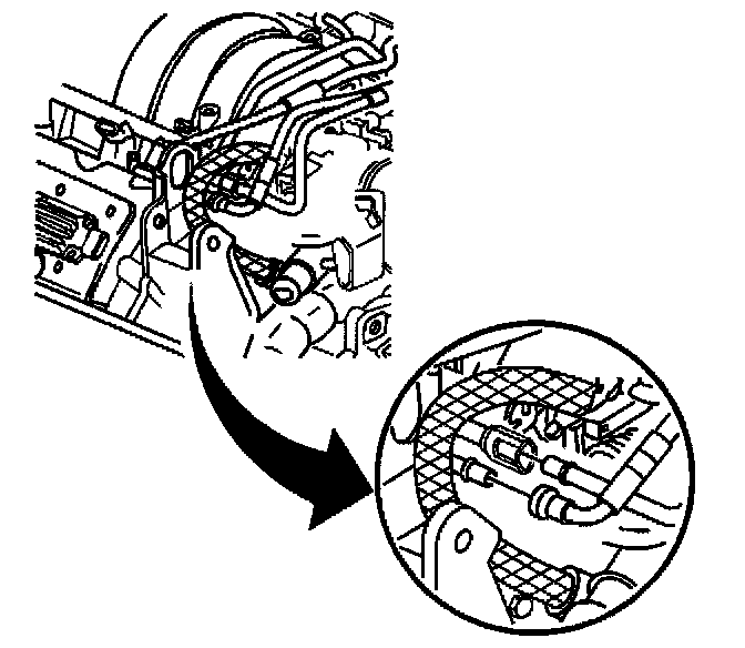
20. Connect the fuel lines to the fuel rail.
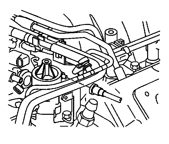
21. Connect the fuel vapor line to the EVAP canister purge solenoid.
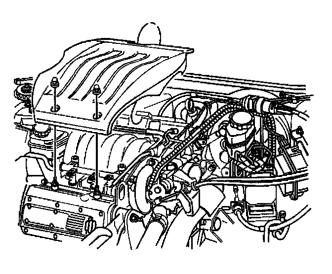
22. Install the fuel injector sight shield.
23. Install the throttle body air inlet duct to the throttle body.
24. Fill the cooling system with engine coolant.
25. Connect the battery ground (negative) cable.