Input Test: II06 (System Monitor Switch) With U68 (VIC) Only
System Monitor Switch Wiring:
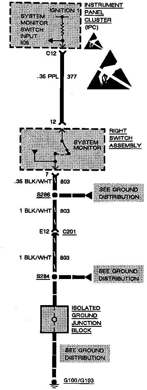
PROPER II06 DIAGNOSTIC DISPLAYS
- HI is displayed with System Monitor Switch released
- LO is displayed with System Monitor Switch depressed
TESTS FOR IMPROPER DISPLAYS
II06 displays HI with System Monitor Switch depressed.
1. Remove Right Switch Assembly. Connect a fused jumper wire between terminals 12 and 7 of Right Switch Assembly Connector.
^ If display reads HI, go to step 2.
^ If display reads LO, check connections. If connections are good, replace Right Switch Assembly.
2. Connect fused jumper wire between terminal 12 of the Right Switch Assembly Connector and ground.
^ If display reads Ht, go to step 3.
^ If display reads LO, check/repair BLK/WHT (803) wire for an open.
3. Remove Instrument Panel Cluster (IPC). Connect an ohmmeter between Instrument Panel Cluster Connector, terminal C12 and Right Switch Assembly Connector, terminal 12.
^ If 0 ohms is measured, replace Instrument Panel Cluster (IPC) if terminal contact is OK.
^ If high resistance is measured, check/repair PPL (377) wire for an open.
II06 displays LO with System Monitor Switch released.
1. Remove Right Switch Assembly.
^ If display reads HI, replace Right Switch Assembly.
^ If display reads LO, go to step 2.
2. Check PPL (377) wire for a short to ground. If PPL (377) wire is OK, replace the Instrument Panel Cluster (IPC).