Service Procedure
1. Write down the owner's preset memory settings which will be lost when the battery is disconnected for reference later when resetting memory functions. If a memory retention device is plugged into the cigarette lighter socket (such as "Memor-Eze", Snap-On Tool YA960, or Kent Moore Tools KS295A or BT9027), this step can be omitted. Then, with the ignition in the "off" position, disconnect the negative battery cable.
CAUTION:
If vehicle is equipped with Inflatable Restraint System (SIR), refer to SUPPLEMENTAL INFLATABLE RESTRAINT Section (9J) of the 1990 Oldsmobile Eighty Eight Royale/Ninety Eight Regency Service Manual. Further, if a memory retention device is used, disconnect the SIR inflator module circuit by disconnecting the YELLOW connector at the base of the steering column. Failure to disconnect the yellow connector may result in airbag deployment with personal injury.
2. Remove instrument panel center trim plate (Torx 15).
3. Remove three screws from cluster trim plate and pull trim plate rearward to remove.
4. Remove five screws from cluster.
5. Remove digital cluster from Instrurnent Panel. The tube to the Automatic Electronic Comfort Control sensor can be removed by twisting it 90 degrees.
6. Remove the two mounting screws on Headlight Switch, and pull the switch rearward. Disconnect the fiber optic lead (it has a small retainer). Remove the panel lamp dimmer switch connector (black) from the Instrument Panel Carrier and pull it out of the panel far enough to allow access to the rear of the connector.
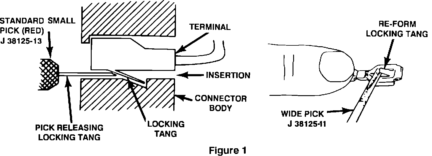
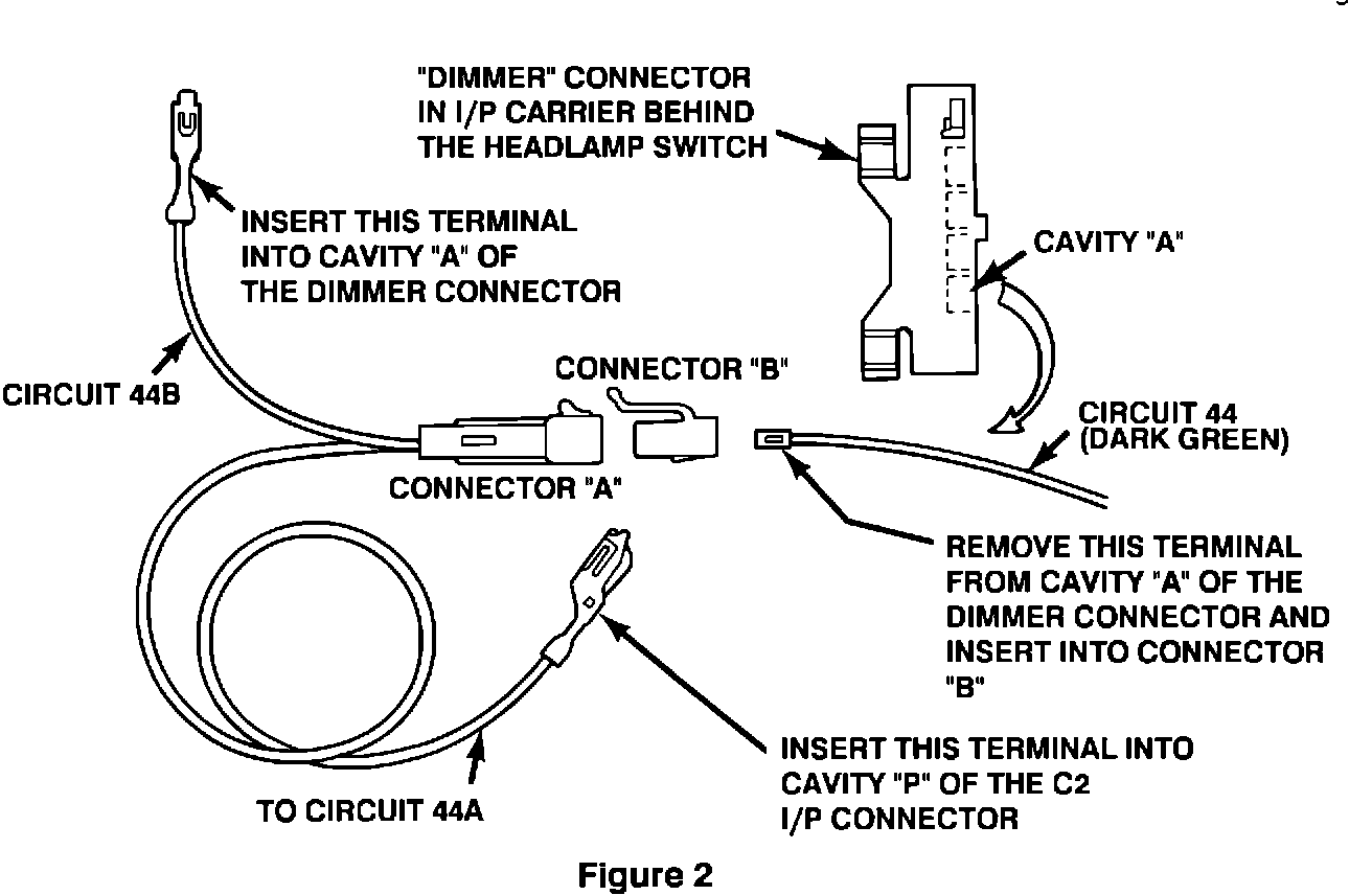
7. Open the terminal cover on the connector. See figure 2. Remove Circuit 44 (dark green) terminal from cavity "A" of the panel lamp dimmer switch connector. Refer to Figure 1 for the proper technique for backing the terminal out of the connector and re-forming the locking tang on the terminal.
8. Obtain Jumper Wire (Service P/N 12102548), and remove connector "B" from connector "A" (see Figure 2). Install the Circuit 44 terminal into connector "B" and plug connector "B" back into "A".
9. Plug the short green wire terminal (labelled "44B" in Figure 2) into the now empty cavity "A" of the panel lamp dimmer switch connector. Close the terminal cover on the connector.
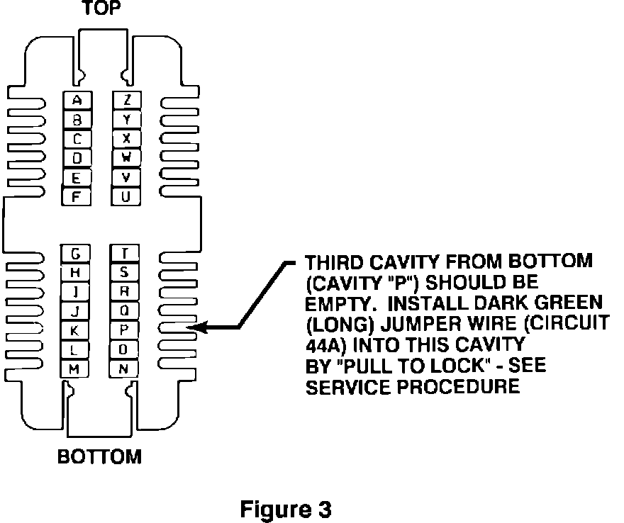
10. Remove cluster connector # 2 (left of the steering column) from the Instrument Panel Carrier. Fish the long green wire on the jumper (labelled "44A" in Figure 2) through the Instrument Panel dimmer connector hole up to the cluster connector # 2. Plug this wire terminal into the empty cavity "P" of connector 2. The bottom edge & locking tab of the terminal fits into a pocket in the connector. Pull on the wire in the direction of the harness to install and lock the terminal into the connector. Refer to Figure 3.
11. Tape the one-way connector "A" and "B" of the jumper to the dimmer harness to prevent rattling. Do not pull any of the three leads taut.
12. Reinstall the panel lamp dimmer switch connector to the Instrument Panel Carrier; plug in the fiber optic lead and reinstall retainer; remount the headlamp switch in the panel and reinstall the two mounting screws. Reinstall Cluster connector # 2 to the Instrument Panel Carrier.
13. Reinstall digital cluster into the instrument panel and reinstall five screws. Reinstall tube to the Automatic Electronic Comfort Control sensor, if previously removed.
14. Reinstall cluster trim plate and three screws. Install center trim plate.
15. Turn on headlamps and cycle panel/cluster lamp dimmer switch to confirm that digital cluster (and other panel lights) call be varied in brightness.
16. Reconnect negative battery cable. If a memory retention device was not used, please reset (to the extent possible) all devices that lost their memory after the battery was disconnected.
17. Install a Campaign Identification Label.