Test A: Isolation Test
1. Remove the connector from the A/C Cut-Out Relay and check the voltage to ground using a test lamp at the following terminals of the connector:Test A Isolation Test Part 1:
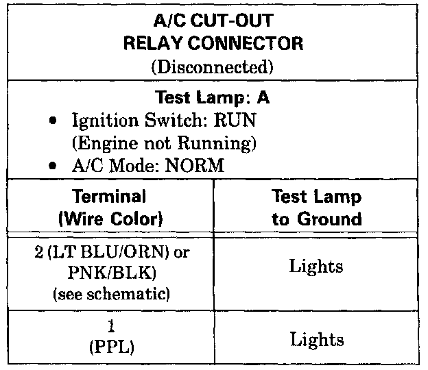
^ If tests are good, proceed to step 2.
^ If test lamp does not light at Terminal 2, check LT BLU/ORN and LT BLU (495) wires and PNK/BLK (639) wires (see schematic). The Idle Speed Power Steering Pressure Switch should be closed.
^ If the test lamp does not light at Terminal 1, jumper the Pressure Cycle Switch and the A/C High Pressure Cut-Out Switch harness connectors.
- If test lamp now lights at Terminal 1 of the A/C Cut-Out Relay, check refrigerant charge. If refrigerant charge is good, replace the suspect pressure switch.
- Check PPL and LT BLU (67) wires for an open.
- If Pressure Cycling Switch is closed and PPL and LT BLU (67) wires are good, proceed to Test D. Test D: A/C Control Assembly Output Test
2. With the connector removed from the A/C Cut-Out Relay, connect a fused jumper between the terminals given in the following table. Note Compressor Clutch action.
Test A Isolation Test Part 2:
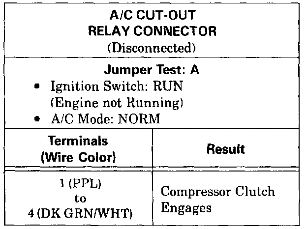
^ If the A/C Compressor Clutch engages (loud click), the clutch and A/C Control Assembly circuits are good. Proceed to Test C. Test C: ECM Compressor Control Test
^ If the A/C Compressor Clutch does not engage proceed to Test B. Test B: A/C Compressor Clutch Test