Recall - Accelerator Cable Inspection/Replacement
88olds09SUBJECT ACCELERATOR CABLE BINDING
MODELS/YEARS CERTAIN 1987 DELTA 88, NINETY-EIGHT AND TOURING SEDAN MODELS
Number: 87-C-11
DATE: May 13, 1988
SECTION: 6C
THIS BULLETIN HAS BEEN UPDATED BY 87-C-11A SECTION 6C, DATED 07-01-88. CONDITION
General Motors has determined that a defect which relates to motor vehicle safety exists in certain 1987 Oldsmobile Delta 88, Ninety-Eight, and Touring Sedan models. Some of these vehicles may have excessive accelerator cable friction restricting the cable's free movement between the accelerator pedal and the throttle body. This friction could be sufficient to prevent the throttle from returning to the closed (idle) position when the accelerator pedal is released. In this event, engine speed may not decrease to a level anticipated by the operator. Loss of accelerator control could result in a vehicle crash without prior warning.

VEHICLES INVOLVED
Involved are certain 1987 Oldsmobile Delta 88, Ninety-Eight, and Touring Sedan vehicles produced within the following vehicle breakpoints:
DEALER ACTION
To prevent this condition, dealers are to inspect and, if required, replace the accelerator control cable on suspected vehicles, per the Vehicles Involved and Service Procedure sections of this bulletin.
Dealers are to perform this campaign on all involved vehicles at no charge to owners, regardless of mileage, age of vehicle, or ownership from this time forward.
Whenever a vehicle subject to this campaign is taken into your new or used car inventory, or it is in your dealership for service, you are to ensure the campaign correction has been made before selling or releasing the vehicle.
Dealers are to contact owners of vehicles recently sold from your new vehicle inventory and arrange for the campaign correction to be performed.
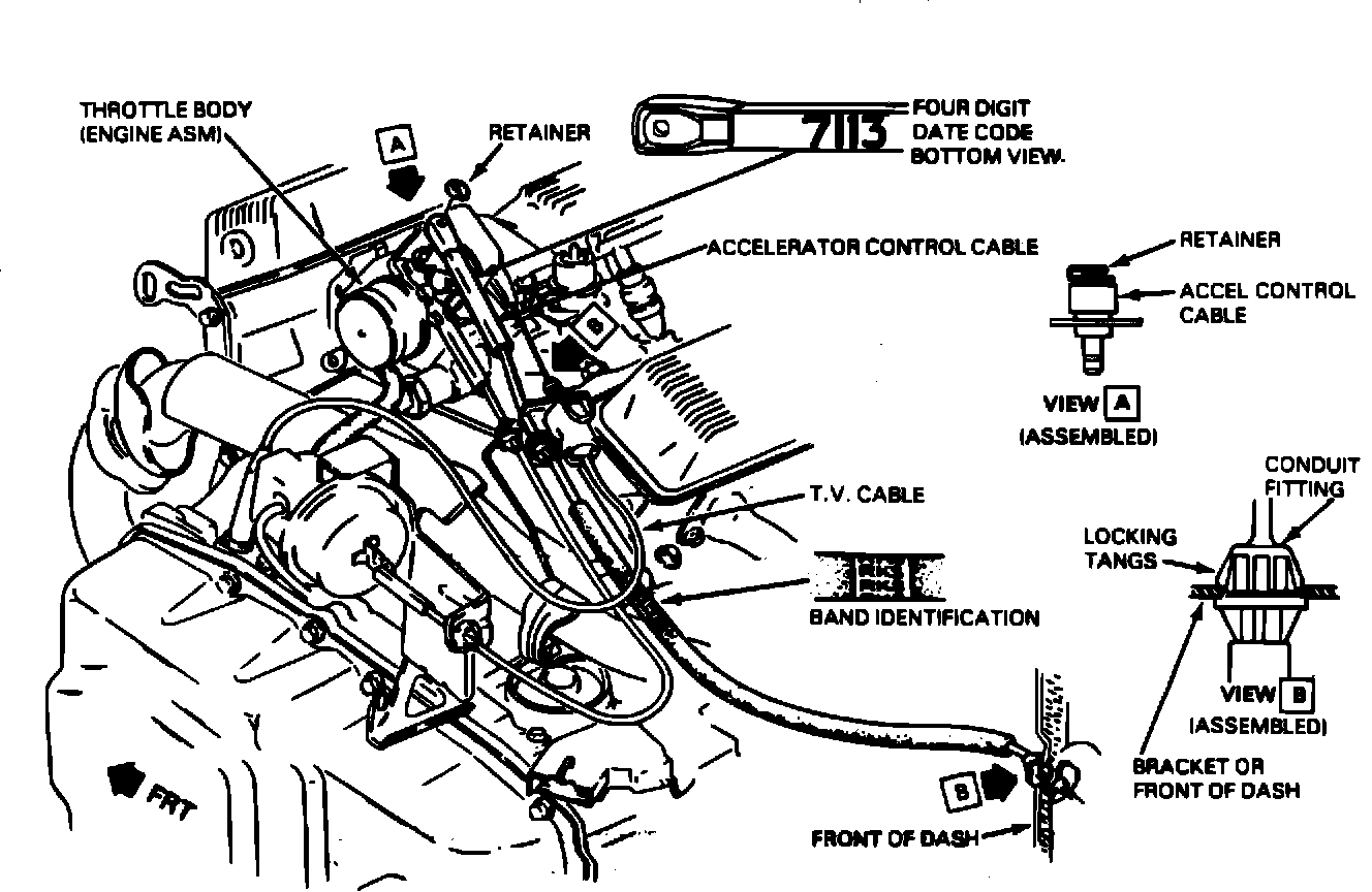
FIGURE 1:
SERVICE PROCEDURE
1. Open hood, and install left fender cover.
2. Inspect accelerator control cable identification band for identification (Figure 1):
^ If band identification is RKS, proceed to Step (3).
^ If band identification is RKT, proceed to Step (10).
3. Inspect accelerator control cable underside at the throttle body end for a four digit, white date code (Figure 1). This can be done with a small mirror, such as a dental mirror.
^ If code is 7113 up to and including 7125, proceed to Step (4).
^ If code is not in the range 7113 up to and including 7125, proceed to Step (10).
4. Remove retainer that attaches accelerator control cable to throttle body stud (Figure 1, View A).
5. Remove accelerator control cable from engine mounted bracket by depressing accelerator control cable locking tangs (Figure 1, View B).
FIGURE 2:
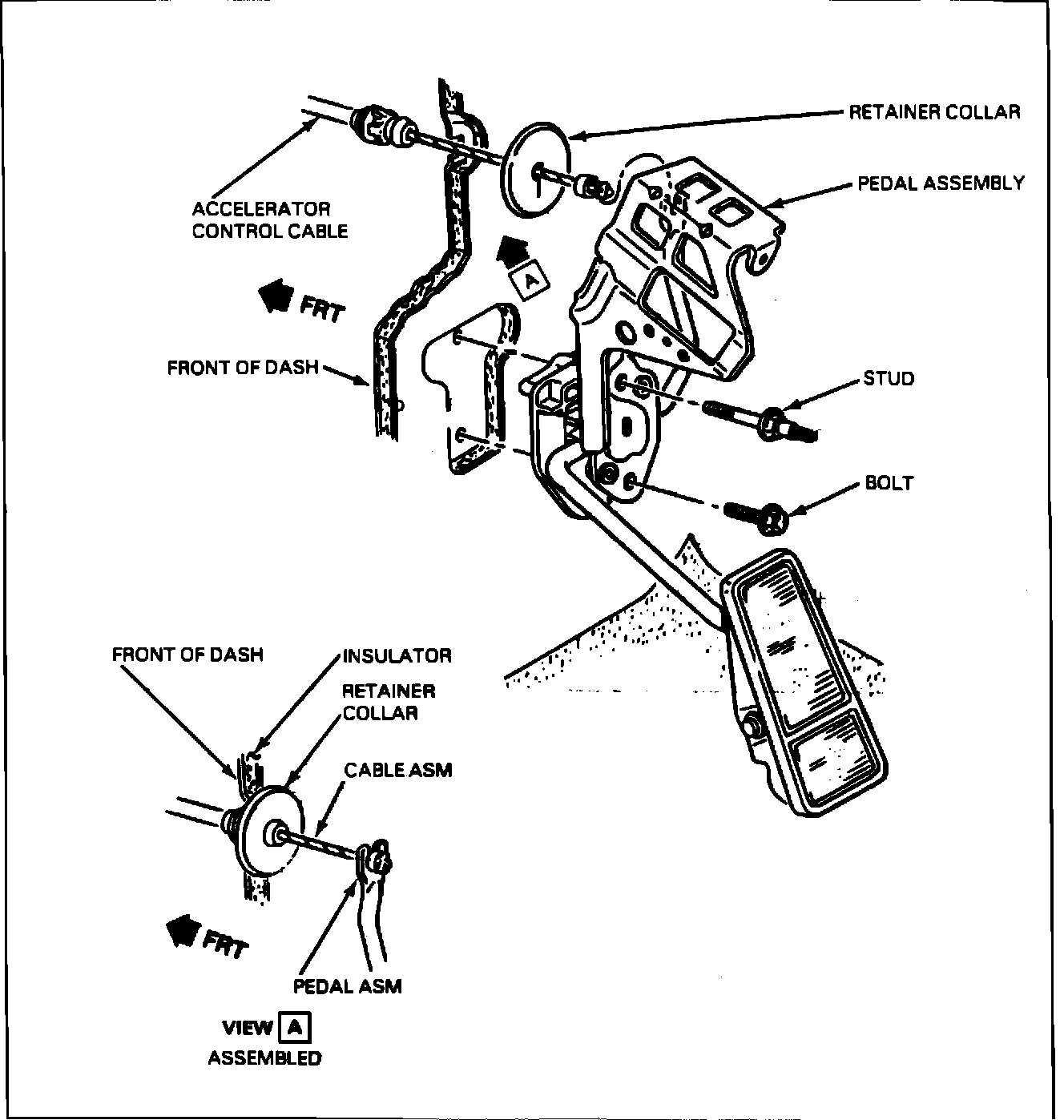
6. Remove lower instrument panel sound insulators and disengage accelerator control cable retainer from accelerator pedal (see Figure 2). Remove retainer collar and reuse on new accelerator control cable.
FIGURE 1:
7. Depress accelerator control cable locking tangs at dash and remove accelerator control cable (Figure 1, View B).
Install new accelerator control cable by reversing the removal procedure. Observe the following during installation of the new accelerator control cable:
Cable Installation
^ Accelerator control cable must be installed in the front of dash prior to assembly to the engine.
^ Accelerator control cable must not be subjected to sharp bends during installation.
^ Accelerator control cable must be routed smoothly and freely of wires, hoses, or other obstructions between conduit fittings.
^ Accelerator control cable must be routed under TV cable.
^ During installation, the braided portion of the accelerator control cable must not come in contact with front-of-dash sealer. This may be accomplished by pulling back on throttle end of the accelerator control cable, keeping braided cable at accelerator pedal end within outer conduit while inserting in front of dash.
^ Locking tangs must be expanded and locked in their attaching holes.
FIGURE 2:
Cable Connection to Accelerator Pedal
^ Install retainer collar from the old accelerator control cable into new accelerator control cable. Refer to Figure 2.
^ Slip accelerator control cable through slot in lever and then install retainer in lever, being sure it is seated. Care must be utilized in pressing the retainer into hole in lever to assure the accelerator control cable is not kinked or damaged in any way (Figure 2).
FIGURE 1:
Cable Connection to Throttle Body Stud
^ Retainer must be installed with tang secured over head of stud (Figure 1, View A).
8. Lube accelerator control cable pivot points with accelerator linkage lubricant, GM Part Number 1052541, or equivalent.
9. Check to ensure that all components are installed correctly and that linkage and accelerator control cable is not rubbing or binding in any manner. Throttle should operate freely without binds between fully closed and wide open throttle positions.
10. Install a Campaign Identification Label.
CAMPAIGN IDENTIFICATION LABEL
Each label provides space to print the campaign number, and the five (5) digit dealer code of the dealer performing the campaign. Insert this information with a typewriter or ballpoint pen. When installing label, clean and dry the surface of the radiator support tie bar and apply the campaign label where it is readily visible.
PARTS INFORMATION
To ensure parts are obtained as soon as possible, order them from GM Service Parts Operations (GMSPO) on a C.I.O. order, with NO special instruction code, but order on an Advise Code (2). Use the following part numbers:
Description Part Number Quantity Per Vehicle
Cable, Accelerator 25533934 1, as required
It is estimated that 25% of vehicles will require an accelerator control cable. Dealers should adjust their orders accordingly.
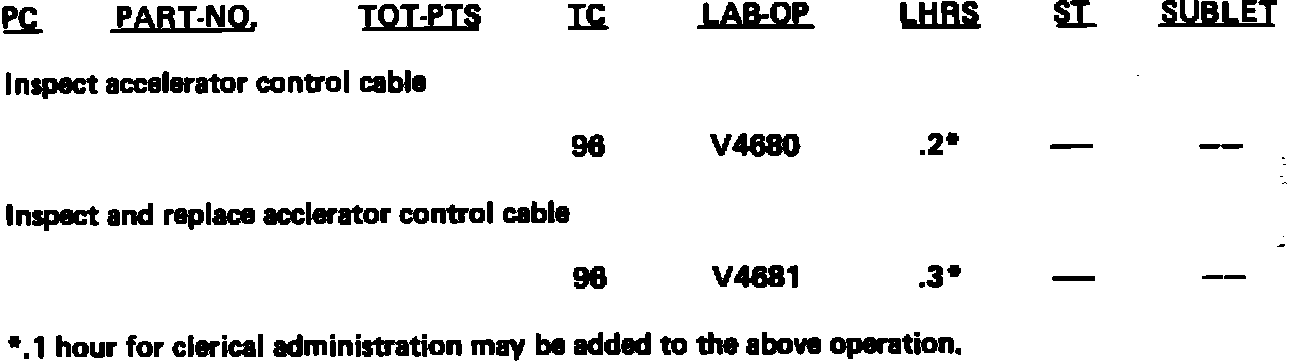
WARRANTY CLAIM INFORMATION
List the one applicable labor operation:
Parts Allowance: Current dealer price, plus 30% allowance for handling.