Evaporator Core: Service and Repair
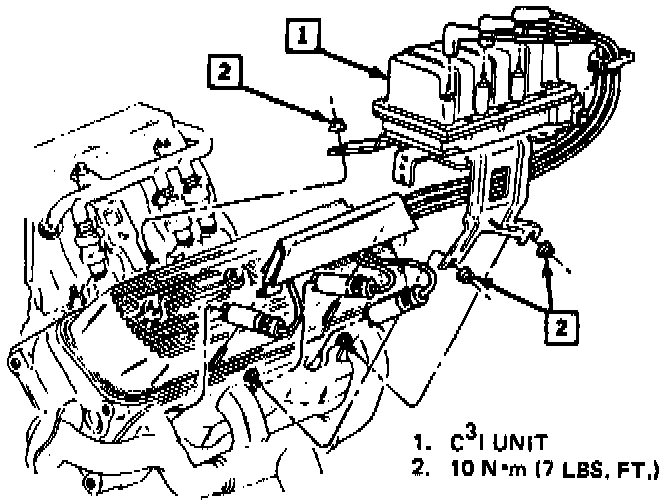
EVRV Solenoid And Coil Pack:
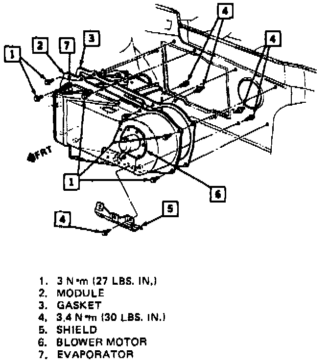
Blower Motor Module:
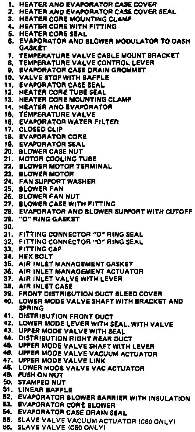
A/C Heater And Evaporator Part 1 Of 2:
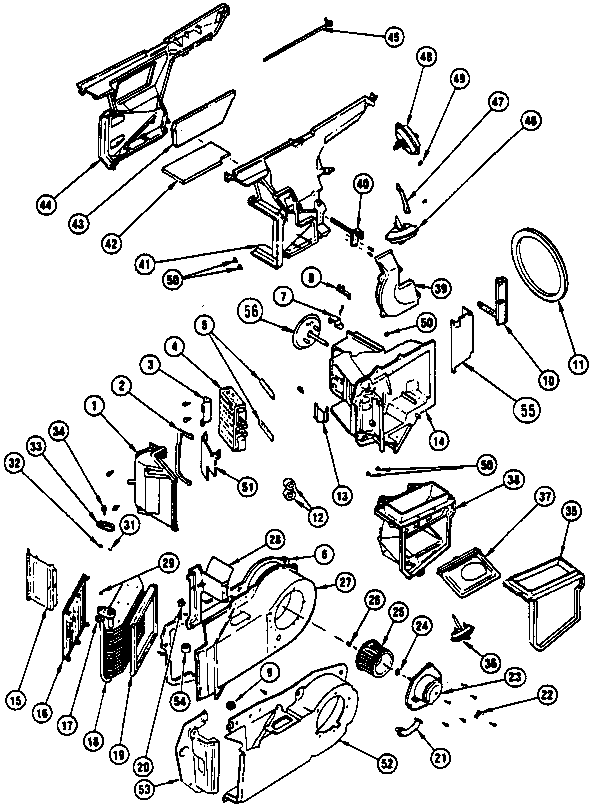
A/C Heater And Evaporator Part 2 Of 2:
REMOVE OR DISCONNECT
1. Negative battery cable.
2. Discharge A/C system.
3. Drain engine coolant.
4. Engine compartment rear sight shield. Refer to Engine Cover Replacement Service and Repair.
5. Four electrical connections and relay bracket assembly.
6. Accumulator to condenser hose.
7. Electrical connector from pressure cycling switch.
8. Evaporator outlet line from accumulator.
9. Accumulator bracket and accumulator install sealing caps.
10. Evaporator tube (condenser to evaporator).
11. Power steering pump and position aside.
12. Spark plug wires from right side (rear bank) plug numbers 2, 4, and 6.
13. Electrical connections from coil pack and EVRV solenoid.
14. Coil bracket assembly and position aside.
15. Vacuum tank.
16. Blower motor including electrical connection and cooling tube.
17. Exhaust manifold heat shield.
18. Heater hoses from heater core.
19. Blower motor resistor.
20. Evaporator outlet line and support bracket.
21. Right hand sound insulator.
22. Floor air outlet duct.
23. Evaporator and blower module bolts (5) from under I.P. (behind carpet).
24. Hoist vehicle.
25. Lower evaporator and blower module bolts (3).
26. Cut rubber blower barrier along guide line (molded into barrier).
27. Lower vehicle.
28. Upper evaporator and blower module bolts (7).
29. Finish cutting rubber barrier along guide lines (molded into barrier).
30. Evaporator from module.
INSTALL OR CONNECT
1. Evaporator into module.
2. Module into vehicle.
^ With strip-caulk, thoroughly seal the seam where the barrier had been cut.
3. Upper evaporator and blower module bolts (7).
4. Hoist vehicle.
5. Lower evaporator and blower module bolts (3).
6. Lower vehicle.
7. Evaporator and blower module bolts (behind carpet) under I.P.
8. Floor air outlet duct.
9. Right hand sound insulator.
10. Evaporator outlet line and support bracket using new "O" ring seals.
11. Blower motor resistor.
12. Heater hoses to heater core.
13. Exhaust manifold heat shield.
14. Blower motor including electrical connection and cooling tube.
15. Vacuum tank.
16. Coil bracket assembly.
17. Electrical connections to coil pack and EVRV solenoid.
18. Three spark plug wires to right side (rear bank) plug
numbers 2, 4, and 6.
19. Power steering pump.
20. Evaporator tube (condenser to evaporator) using new "O" ring seals.
21. Accumulator and bracket using new "O" ring seals.
^ Remove sealing caps just prior to connecting refrigerant lines.
22. Evaporator outlet line to accumulator.
23. Electrical connector to pressure cycling switch.
24. Accumulator to condenser hose.
25. Four electrical connections and relay bracket assembly.
26. Engine compartment rear sight shield. Refer to Engine Cover Replacement Service and Repair.
27. Negative battery cable.
28. Refill engine coolant.
29. Evacuate, charge, and leak test system.