Front Suspension
Front Wheel AlignmentDESCRIPTION
NOTE: Before checking the front wheel alignment, be sure to make a preliminary inspection (Unladen*).
*: Fuel, radiator coolant and engine oil full. Spare tire, jack, hand tools and mats in designated positions.
PRELIMINARY INSPECTION
^ Check the tires for wear and improper inflation.
^ Check the wheel runout.
Wheel runout: Refer to WT-5, "Inspection". Testing and Inspection
^ Check the front wheel bearings for looseness. Check the front suspension for looseness. Check the steering linkage for looseness.
^ Check that the front shock absorbers work properly.
^ Check the vehicle height (posture) in the unladen condition. Refer to FSU-5, "On-vehicle Service". Front Suspension
GENERAL INFORMATION AND RECOMMENDATIONS
1. A Four-Wheel Thrust Alignment should be performed.
^ This type of alignment is recommended for any NISSAN vehicle.
^ The four-wheel "thrust" process helps ensure that the vehicle is properly aligned and the steering wheel is centered.
^ The alignment machine itself should be capable of accepting any NISSAN vehicle.
^ The alignment machine should be checked to ensure that it is level.
2. Make sure the alignment machine is properly calibrated.
^ Your alignment machine should be regularly calibrated in order to give correct information.
^ Check with the manufacturer of your specific alignment machine for their recommended Service/Calibration Schedule.
THE ALIGNMENT PROCESS
IMPORTANT: Use only the alignment specifications listed in this Service Manual. Refer to FSU-19, "Front Wheel Alignment (Unladen*1)". Front Wheel Alignment (Unladen*1)
1. When displaying the alignment settings, many alignment machines use "indicators": (Green/red, plus or minus, Go/No Go). Do NOT use these indicators.
^ The alignment specifications programmed into your alignment machine that operate these indicators may not be correct.
^ This may result in an ERROR.
2. Some newer alignment machines are equipped with an optional "Rolling Compensation" method to "compensate" the sensors (alignment targets or head units). Do NOT use this "Rolling Compensation" method.
^ Use the "Jacking Compensation" method. After installing the alignment targets or head units, raise the vehicle and rotate the wheels 1/2 turn both ways.
^ See Instructions in the alignment machine you are using for more information.
CAMBER, CASTER AND KINGPIN INCLINATION
NOTE: Camber, caster and kingpin inclination are preset at factory and cannot be adjusted.
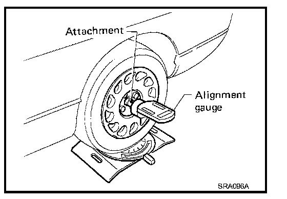
1. Measure the camber, caster and kingpin inclination of both the right and left wheels using attachment Tool and a suitable alignment gauge.
Camber, caster and kingpin inclination: Refer to FSU-19, "Front Wheel Alignment (Unladen*1)". Front Wheel Alignment (Unladen*1)
2. If the camber, caster or kingpin inclination is not within specification, inspect the front suspension parts. Replace any damaged or worn out parts.
TOE-IN
WARNING:
^ Always perform the following procedure on a flat surface.
^ Make sure that no person is in front of the vehicle before pushing it.
1. Bounce the front of vehicle up and down to stabilize the vehicle height (posture).
2. Push the vehicle straight ahead about 5 m (16 ft).
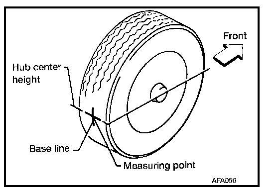
3. Put a mark on base line of the tread (rear side) of both front tires at the same height as hub center as shown. These marks are measuring points.
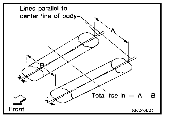
4. Measure the distance "A" on the rear side of the front tires as shown.
5. Push the vehicle slowly ahead to rotate the wheels 180° degrees (1/2 a turn).
CAUTION: If the wheels have rotated more than 180° degrees (1/2 turn), start this procedure again from the beginning. Never push the vehicle backward.
6. Measure the distance "B" on the front side of the front tires at the same marks as shown.
Total toe-in: Refer to FSU-19, "Front Wheel Alignment (Unladen*1)". Front Wheel Alignment (Unladen*1)
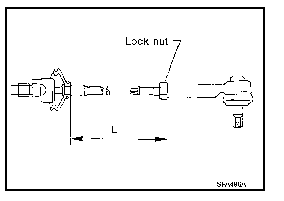
7. Adjust the toe-in by varying the length of the steering outer tie-rods.
a. Loosen the outer tie-rod lock nuts.
b. Adjust the toe-in by screwing the outer tie-rods in or out.
Standard length "L": Refer to PS-30, "Steering Gear and Linkage". [1][2]Specifications
c. Tighten the outer tie-rod lock nuts to specified torque.
Lock nut: Refer to PS-19, "Removal and Installation". Removal and Replacement
FRONT WHEEL TURNING ANGLE
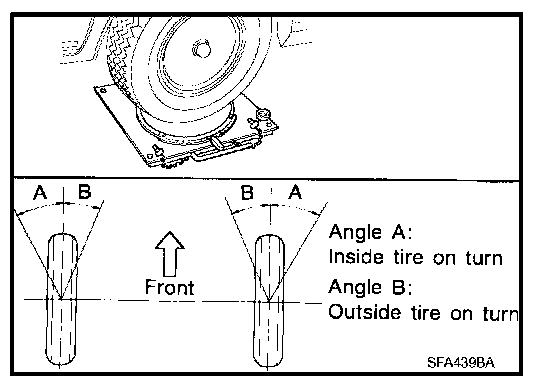
1. Set the front wheels in a straight-ahead position. Then move the vehicle forward until the front wheels rest on the turning radius gauge as shown.
2. Rotate steering wheel all the way right and left; measure the turning angles "A" and "B" as shown.
Wheel turning angle (full turn): Refer to FSU-19, "Front Wheel Alignment (Unladen*1)". Front Wheel Alignment (Unladen*1)