Traction Control Module: Service and Repair
ACTUATOR AND ELECTRIC UNIT (ASSEMBLY)Removal and Installation
BRC-48 Component:
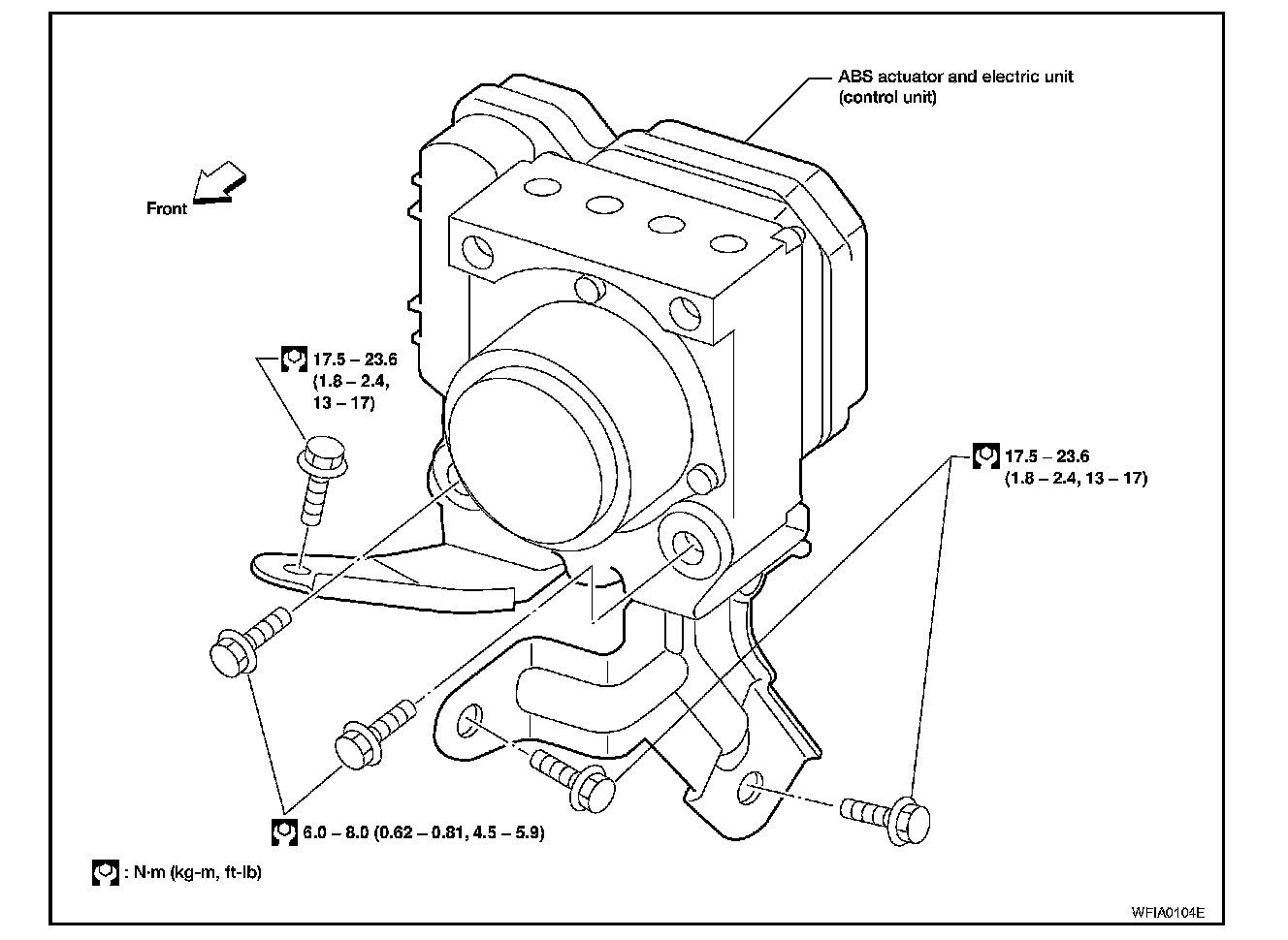
REMOVAL
1. Disconnect battery negative terminal.
2. Remove windshield wiper and linkage assembly.
3. Drain brake fluid.
4. Discharge the A/C refrigerant.
5. Disconnect and remove high-pressure and low-pressure A/C pipes to allow access to ABS actuator and electric unit (control unit).
6. Disconnect harness connectors from ABS actuator and electric unit (control unit).
7. Disconnect brake pipes, noting their location for installation.
8. Remove bolts and ABS actuator and electric unit (control unit).
INSTALLATION
CAUTION:
After installation of ABS actuator and electric unit (control unit), refill brake fluid. Then bleed air from system.
1. Position ABS actuator and electric unit (control unit) in vehicle.
2. Connect brake pipes and bolts temporarily.
3. Tighten bolts and brake pipes to specification. Refer to BR-8, "Hydraulic Circuit". Diagrams
4. Connect ABS actuator and electric unit (control unit) harness connectors.
5. Install and connect high-pressure and low-pressure A/C pipes.
6. Install windshield wiper and linkage assembly.
7. Connect battery negative terminal.
8. Evacuate and recharge the A/C system.
9. Adjust the steering angle sensor. Refer to BRC-45, "Adjustment of Steering Angle Sensor Neutral Position". Testing and Inspection