Front
Wheel Alignment InspectionDESCRIPTION
- Measure wheel alignment under unladen conditions.
NOTE: Unladen conditions mean that fuel, engine coolant, and lubricant are full. Spare tire, jack, hand tools and mats are designated positions.
PRELIMINARY CHECK
1. Check tires for improper air pressure and wear.
2. Check road wheels for runout.
3. Check wheel bearing axial end play.
4. Check ball joint axial end play of compression rod, upper link, and steering knuckle
5. Check shock absorber operation.
6. Check each mounting part of axle and suspension for looseness and deformation.
7. Check each link, rod and member for cracks, deformation and other damage.
8. Check vehicle posture.
INSPECTION OF CAMBER, CASTER AND KINGPIN INCLINATION ANGLES
- Camber, caster, kingpin inclination angles cannot be adjusted.
- Before inspection, mount front wheels onto turning radius gauge. Mount rear wheels onto a stand that has same height so vehicle will remain horizontal.
Using a CCK Gauge
Install CCK gauge attachment (SST: KV991040S0) as following procedure in wheel, then measure wheel alignment.
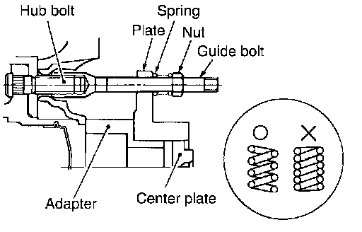
1. Remove wheel nuts (2), and install a guide bolt to hub bolt.
2. Screw adapter into plate body until it contacts body tightly.
3. Screw center plate into plate.
4. Insert plate on guide bolt. Put spring in, and then evenly screw both guide bolt nut. When fastening guide bolt nut, do not completely compress spring.
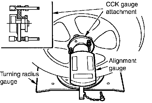
5. Place the dent of alignment gauge onto the projection of center plate and tightly contact them to measure.
Standard value
Camber, caster, kingpin inclination angles: Refer to "SERVICE DATA".
CAUTION:
- If camber, caster, or kingpin inclination angle is outside the standard, check front suspension parts for wear and damage, and replace suspect parts if necessary.
- King pin inclination angle is reference value, no inspection is required. (Due to the type of suspension, the kingpin inclination angle cannot be measured correctly using a normal alignment tester.)
Toe-In Inspection
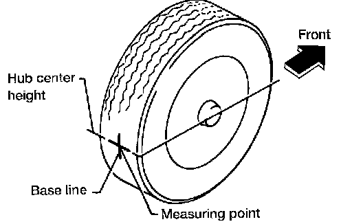
Measure toe-in using the following procedure.
WARNING:
- Always perform the following procedure on a flat surface.
- Make sure that no person is in front of vehicle before pushing it.
1. Bounce front of vehicle up and down to stabilize the posture.
2. Push vehicle straight ahead about 5 meters (16 ft.).
3. Put a mark on base line of the tread (rear side) of both tires at the same height of hub center. These are measuring points.
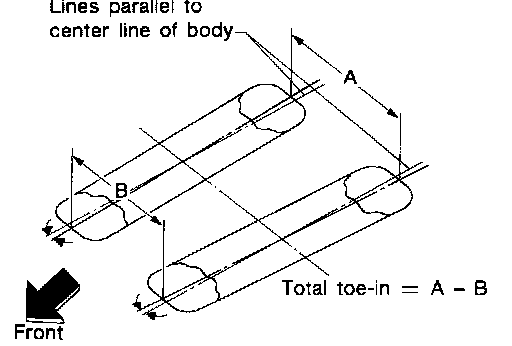
4. Measure distance "A" (rear side).
5. Push vehicle slowly ahead to rotate wheels 180 degrees (1/2 turn).
If wheels have rotated more than 180 degrees (1/2 turn), try the above procedure again from the beginning. Never push vehicle backward.
6. Measure distance "B" (front side).
Standard value
Total toe-in: Refer to "SERVICE DATA".
Part 1:
Part 2:

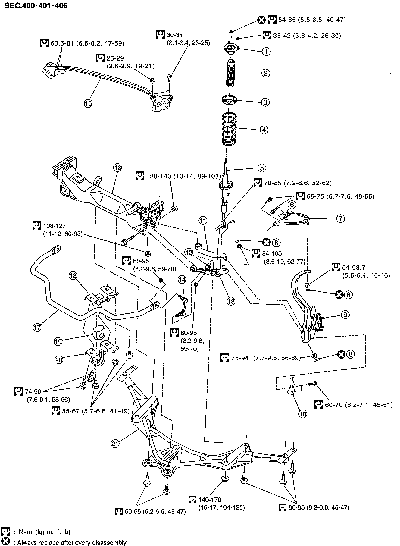
Components
Removal and Installation
REMOVAL
1. Remove tire with power tool.
2. Remove brake caliper with power tool. Hang it in a place where it will not interfere with work. Refer to "FRONT DISC BRAKE (CLZ25VD TYPE)", "FRONT DISC BRAKE (OPB27VA TYPE)".
3. Remove undercover with power tool.
4. Remove fixing bolts and nuts, then remove front cross bar from vehicle with power tool.
5. Remove steering hydraulic piping bracket from front suspension member.
6. Remove steering gear and front suspension member attachment bolts and hang steering gear on vehicle.
7. Set jack under engine.
CAUTION: When setting jack to engine, use a wooden block or an equivalent for the setting.
8. Remove fixing bolt and nut between shock absorber and transverse link with power tool.
9. Remove cotter pin of upper link ball joint, then loosen mounting nut.
10. Use a ball joint remover (suitable tool) to remove upper link from steering knuckle. Be careful not to dam age ball joint boot.
CAUTION: Tighten temporarily mounting nut to prevent damage to threads and to prevent ball joint remover (suitable tool) from coming off.
11. Remove fixing nut and washer located at the bottom of stabilizer connecting rod, and then remove stabilizer connecting rod from transverse link with power tool.
12. Remove fixing nuts between engine mounting insulator and front suspension member. Refer to "ENGINE ASSEMBLY".
13. Remove fixing nuts between front suspension member and body with power tool.
14. Remove front suspension assembly form vehicle.
INSTALLATION
- Refer to "Components" for tightening torque. Install in the reverse order of removal.
NOTE: Refer to component parts location and do not reuse non-reusable parts.
- Perform final tightening of shock absorber lower side (rubber bushing) under unladen condition with tires on ground. Check wheel alignment. Refer to "SERVICE DATA".