Disassembly and Assembly
FRONT DISC BRAKE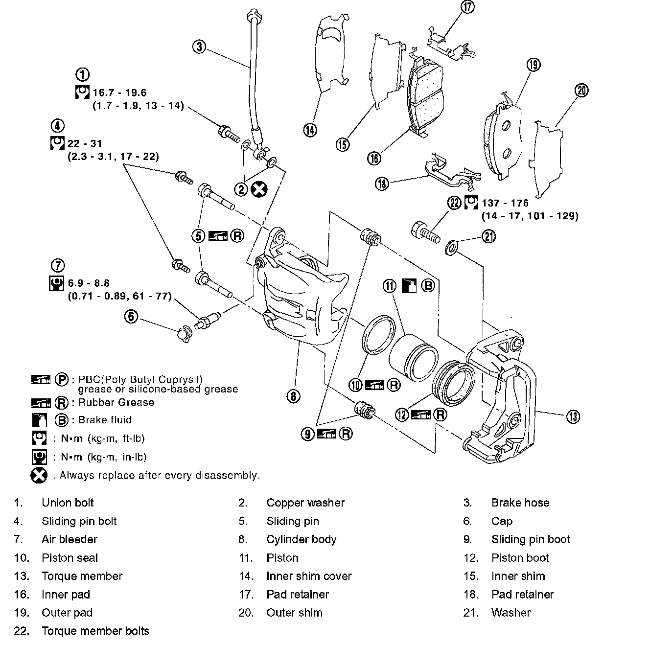
Component
CAUTION:
- Clean dust on caliper and brake pad with a vacuum dust collector. Do not blow with compressed air.
- While the brake pad and cylinder body are separated, the piston may suddenly jump out, so do not depress the brake pedal.
- It is not necessary to remove bolts on torque member and brake hose except for disassembly or replacement of the caliper assembly. In this case, hang cylinder body with a wire so that brake hose is not under tension.
- Do not damage piston boot.
- If any shim is subject to serious corrosion, replace it with a new one.
- Always replace shims and shim covers as a set when replacing brake pads.
- Keep the rotor clean of brake fluid.
- Burnish the brake contact surfaces when refinishing or replacing brake rotors, after replacing pads or linings, or if a soft pedal occurs at very low mileage.
Disassembly and Assembly of Caliper Assembly
DISASSEMBLY
1. Remove the sliding pin bolt, and then remove the pad, shim, shim cover, and pad retainer from the torque member.
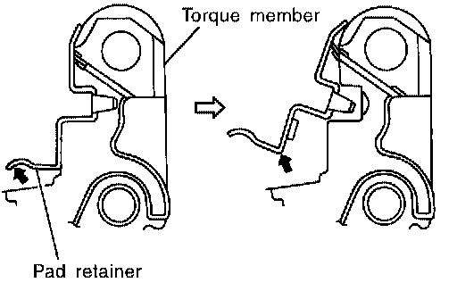
CAUTION: When removing the pad retainer from the torque member, lift it in the direction indicated by the arrow in the figure so that it does not deform.
2. Remove sliding pins and sliding pin boots from torque member.
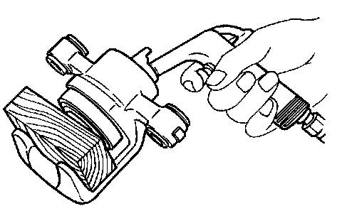
3. Place a wooden block as shown, and blow air from union bolt mounting hole to remove pistons and piston boots.
CAUTION: Do not get your fingers caught in the piston.
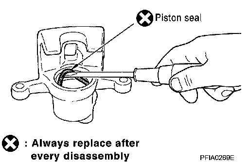
4. Remove the piston seal from the cylinder body using a screwdriver or suitable tool.
CAUTION: Be careful not to damage cylinder inner wall. every disassembly
CALIPER INSPECTION
Cylinder Body
CAUTION:
- Use new brake fluid to clean. Never use mineral oils such as gasoline or kerosene.
- Check for corrosion, wear, or damage to the cylinder inner wall, and replace the caliper if there are any non standard conditions.
- Minor flaws caused by corrosion or a foreign material can be removed by polishing the surface with a fine sandpaper. Replace the cylinder body, if necessary.
Torque Member
Check for wear, cracks, and damage. If damage or deformation is present, replace the affected part.
Piston
CAUTION:
- Since the piston surface is plated, do not repair using sandpaper.
- Check piston surface for corrosion, wear, and damage. If any non-standard condition is detected, replace applicable part.
Sliding Pins, Sliding Pin Bolts, and Sliding Pin Boots
Check sliding pins, sliding pin bolts, and sliding pin boot for wear, damage, and cracks. If damage or deformation is present, replace the affected part.
ASSEMBLY
CAUTION: Do not use Nissan Rubber Grease (KRE00 00010 or KRE00 00010 01) when assembling.
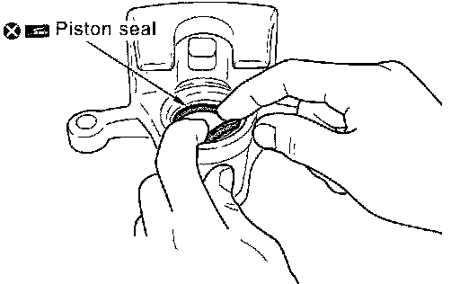
1. Apply rubber grease to the piston seal and attach to cylinder body.
CAUTION: Do not reuse the piston seals.
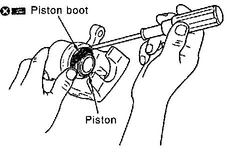
2. Apply brake fluid or rubber grease to the piston boot, place it on the piston, and firmly insert the piston boot cylinder-side lip into the cylinder body groove.
CAUTION: Do not reuse the piston boot.
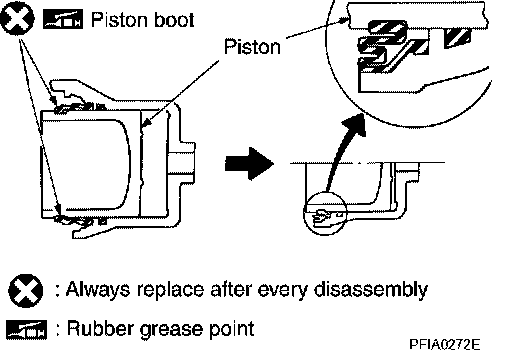
3. Apply brake fluid or rubber grease to the piston, insert into the cylinder body by hand and firmly attach the piston boot piston side lip into the piston groove.
CAUTION: Press the piston evenly and vary the pressing point to prevent cylinder inner wall from being rubbed.
4. Install sliding pins and sliding pin boots to torque member.
5. Attach the inner shim and shim cover to the inner pad and the outer shim to the outer pad.
6. Install cylinder body. Tighten sliding pin bolt to the specified torque.
DISC ROTOR INSPECTION
Visual Inspection
Check surface of the disc rotor for uneven wear, cracks, and serious damage. If any non-standard condition is detected, replace applicable part.
Runout Inspection
1. Using wheel nuts, fix disc rotor to the wheel hub in 2 or more positions.
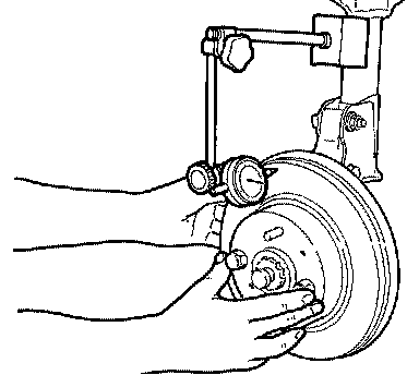
2. Inspect runout using a dial gauge.
Standard value (measured at 10 mm (0.39 inch) inside the disc edge)
Runout limit (with it attached to the vehicle) : 0.07 mm (0.0028 inch) or less
CAUTION: Before measuring, make sure the axle endplay is 0 mm (0 inch).
3. If runout is outside the limit, find the minimum runout point by shifting mounting positions of the disc rotor and wheel hub by one hole.
Thickness Inspection
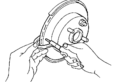
Using a micrometer, check thickness of the disc rotor. If thickness does not meet specification, replace disc rotor.
Standard thickness : 28 mm (1.10 inch)
Minimum thickness : 26 mm (1.02 inch)
Maximum uneven wear (measured at 8 positions) : 0.015 mm (0.0006 inch) or less